VVNB — HA NOI/Noi Bai International
VVNB AD 2.1 AERODROME LOCATION INDICATOR AND NAME
VVNB — HA NOI/Noi Bai International
VVNB AD 2.2 AERODROME GEOGRAPHICAL AND ADMINISTRATIVE DATA
| 1 | ARP coordinates and site at AD | 211318N – 1054820E Intersection of RWY 11L/29R and TWY N3 | ||||||||||||||||
| 2 | Direction and distance from Ha Noi city | 28 KM North from Ha Noi city | ||||||||||||||||
| 3 | Elevation/Reference temperature | 13 M/33°C | ||||||||||||||||
| 4 | Geoid undulation at AD ELEV PSN | Nil | ||||||||||||||||
| 5 | Magnetic (MAG) variation (VAR)/ Annual change | 2° W (2022) | ||||||||||||||||
| 6 | Name of aerodrome operator, address, telephone, telefax numbers, e-mail address,AFS address and, if available, website afdress |
| ||||||||||||||||
| 7 | Types of traffic permitted (IFR/VFR) | IFR/VFR | ||||||||||||||||
| 8 | Remarks | Nil |
VVNB AD 2.3 OPERATIONAL HOURS
| 1 | Aerodrome Administration | H24 |
| 2 | Customs and Immigration | H24 |
| 3 | Health and Sanitation | H24 |
| 4 | AIS Briefing Office (AIS) | H24 |
| 5 | ATS Reporting Office (ARO) | H24 |
| 6 | MET Briefing Office | H24 |
| 7 | Air traffic services (ATS) | H24 |
| 8 | Fuelling | H24 |
| 9 | Handling | H24 |
| 10 | Security | H24 |
| 11 | De-icing | Nil |
| 12 | Remarks | Nil |
VVNB AD 2.4 HANDLING SERVICES AND FACILITIES
| 1 | Cargo-handling facilities | Conveyor belts and fork lift |
| 2 | Fuel/oil types | JET A1, RH91/115; Oil:MC20, MK8 |
| 3 | Fuelling facilities/capacity | 2 trucks 10 000US Gall; 1 truck 23 000 litters and 2 trucks 30 000 litters, Fuel hydrant system for Terminal 2 |
| 4 | De-icing facilities | Nil |
| 5 | Hangar space for visiting aircraft | Nil |
| 6 | Repair facilities for visiting aircraft | Available for aircraft AN24, AN30, YAK40, TU134, A320, B767 |
| 7 | Remarks | Nil |
VVNB AD 2.5 PASSENGER FACILITIES
| 1 | Hotels | Near the AD and in the city |
| 2 | Restaurants | At Aerodrome and in the city |
| 3 | Transportation | Buses, taxis and car hire |
| 4 | Medical facilities | First aid at AD. Hospitals in the city |
| 5 | Bank and Post Office | At AD. Open 0001 - 1100 UTC |
| 6 | Tourist Office | Office in the city |
| 7 | Remarks | Nil |
VVNB AD 2.6 RESCUE AND FIRE FIGHTING SERVICES
| 1 | AD category for fire fighting | CAT 9 |
| 2 | Rescue equipment | Adequately provided as recommended by ICAO |
| 3 | Capability for removal of disabled ACFT | Nil |
| 4 | ||
Remarks | All airport emergency service personnel are trained in rescue and fire fighting as well as medical first-aid. |
VVNB AD 2.7 SEASONAL AVAILABILITY – CLEARING
There is no requirement for clearing as the aerodrome is available throughout the year.
VVNB AD 2.8 APRONS, TAXIWAYS AND CHECK LOCATIONS/POSITIONS DATA
| 1 | Apron surface and strength | Surface: | Cement concrete | ||
Strength: | - Apron PCN 66/R/B/W/T - Apron - Hangar | ||||
| 2 | Taxiway | (Connecting TWY) | S1 | Width: | 23 M |
Surface: | Cement | ||||
Strength: | PCN 98/R/B/W/T | - The portion from the beginning of RWY 11R to the intersection of TWY S1 and TWY S7/S7A: PCN 98/R/B/W/T. - The portion from the intersection of TWY S1 and TWY S7/S7A to the intersection of TWY S1 and TWY S2/S2A: PCN 65/R/B/W/T. - The portion from the beginning of RWY 29R to the intersection of TWY S1 and TWY S2/S2A: PCN 95/R/B/W/T. | |||
(Connecting TWY) | S1A | Width: | 23 M | ||
Surface: | Cement concrete | ||||
Strength: | PCN 95/R/B/W/T | ||||
(Connecting TWY) | S1B | Width: | 23 | ||
Surface: | Cement concrete | ||||
Strength: | PCN 96 | ||||
(Parallel TWY) | S1C | Width: | 23 | ||
Surface: | Cement concrete | ||||
Strength: | - A portion from the beginning of RWY 11R to the intersection of TWY S1 and TWY S3/V3: PCN 98/R/B/W/T. - A portion from the intersection of TWY S1 and TWY S3/V3 to the intersection of TWY S8/V8: PCN 65/R/B/W/T. - A portion from the intersection of TWY S8/V8 to the beginning of RWY 29L: PCN 95/R/B/W/T. | PCN 65/R/B/W/T | |||
| 2 | Taxiway | (Connecting TWY) | S1D | Width: | 23 |
Surface: | Cement concrete | ||||
Strength: | PCN 54 | ||||
(Rapid | Width: | 28 | |||
Surface: | Cement concrete | ||||
Strength: | PCN 97 | ||||
(Connecting TWY) | S2 | Width: | 23 M | ||
Surface: | Cement concrete | ||||
Strength: | PCN 97 | ||||
(Connecting TWY) | S2A | Width: | 27 | ||
Surface: | Cement concrete | ||||
Strength: | PCN 60-70 | ||||
(Rapid exit TWY) | S2B | Width: | 27 | ||
Surface: | Cement concrete | ||||
Strength: | PCN 65 | ||||
(TWY on apron) | S3 | Width: | 23 M | ||
Surface: | Cement concrete | Cement concrete | |||
Strength: | - A portion from the beginning of RWY 11R to TWY V7 on apron 1: PCN 66/R/B/W/T. - A portion from TWY V7 to TWY V8 on Hangar apron: PCN 54/R/B/W/T. - A portion on apron 2: PCN 85/R/B/W/T. | PCN 96/R/B/W/T | |||
| S4 | Width: | 27 M | |||
Surface: | Cement concrete | ||||
Strength: | PCN 60 - 70/R/C/W/U | ||||
| S5 | Width: | 23 M | |||
Surface: | Cement concrete | ||||
Strength: | PCN 96/R/B/W/T |
| 2 | Taxiway | (Connecting TWY) | S5A | Width: | 23 |
Surface: | Cement concrete | ||||
Strength: | PCN 65/R/B/W/T | ||||
| S6 | Width: | 23 M | |||
Surface: | Cement concrete | ||||
Strength: | PCN 97/R/B/W/T | ||||
(Connecting TWY) | S6A | Width: | 38 | ||
Surface: | Cement concrete | Cement concrete | |||
Strength: | PCN 65 | ||||
(Connecting TWY) | Width: | 30 M | |||
Surface: | Cement concrete | ||||
Strength: | PCN 85/R/B/W/T | ||||
(Main Northern TWY) | Width: | 14 M | |||
Surface: | Cement concrete | ||||
Strength: | PCN 54/R/C/W/U | ||||
| N1, N2, N3, N4, N5 | Width: | 14 M | |||
Surface: | Cement concrete, bituminous concrete | ||||
Strength: | PCN 54/R/C/W/U | ||||
| S6B | Width: | 28 M | |||
Surface: | Cement concrete | ||||
Strength: | PCN 97/R/B/W/T | ||||
| S7 | Width: | 23 M | |||
Surface: | Cement concrete | ||||
Strength: | PCN 54/R/C/W/U | ||||
| S7A | Width: | 38 M | |||
Surface: | Cement concrete | ||||
Strength: | PCN 65/R/B/W/T | ||||
| P4 | Width: | 23 M | |||
Surface: | Cement concrete | ||||
Strength: | PCN 95/R/B/W/T | ||||
| P7 | Width: | 23 M | |||
Surface: | Cement concrete | ||||
Strength: | PCN 95/R/B/W/T | ||||
Main Northern TWY | Width: | 14 M | |||
Surface: | Cement concrete | ||||
Strength: | PCN 54/R/C/W/U | ||||
| N1, N2, N3, N4, N5 | Width: | 14 M | |||
Surface: | Cement concrete, bituminous concrete | ||||
Strength: | PCN 54/R/C/W/U | ||||
| 3 | Altimeter checkpoint location and elevation | Location: | Nil | ||
Elevation: | Nil | ||||
| 4 | VHF | 4 VOR checkpoints: - 211326.90N 1054732.36E - 211322.73N 1054710.88E - 211259.86N 1054824.02E - Located on TWY S1 between RWY 29L and RWY 29R. | |||
| 5 | INS checkpoints | Nil | |||
| 6 | Remarks | Apron | - A | ||
TWY P3 | - Do not use for the RWY 11L/29R- holding position when there is aircraft take-off and landing on RWY 11R/29L. - Do not use for the RWY 11R/29L- holding position at the North when there is aircraft take-off and landing on RWY 11L/29R (due to distance between 2 the holding positions are APRX 30 M). | ||||
TWYs | Do | ||||
TWYs | One-way | ||||
TWY S5A | One-way use via vacating RWY 11R/29L. | ||||
TWY S9 | Do | ||||
TWYs | Two | ||||
TWY V1 | Closure 36 M of TWY V1 (a portion of 51 M from the centre line of TWY S to the South to a portion of 11.5 M from centre line of TWY C to the North) to arrange stands 8, 9, 10. | ||||
- Aircraft code D (wingspan from 36 M) and above is not only taxi/towed, pushed via TWY V (portion from stand 12 to the West when there is aircraft parking at stand 12C or 12D. - Aircraft code F (wingspan from 68.5 M) and above is only allowed to taxi or towed/pushed via TWY V3/V4/V5 into stand or depart for stands 14, 28 and taxi via TWY V9 into stand or depart for stands 75A and 79A. | |||||
| Vệt lăn | |||||
Dimensions of the turn pad | - RWY 11L : 106 x 58.5 x 48 M. - RWY 29R: 118 x 74 x 31.5 M. | ||||
VVNB AD 2.9 SURFACE MOVEMENT GUIDANCE AND CONTROL SYSTEM AND MARKINGS
| 1 | |||
Use of aircraft stand ID signs, TWY guide lines and visual docking/parking guidance system of aircraft stands | Taxiing guidance signs at all intersections with TWY, RWY and at all holding positions. Guide lines at apron. Visual Docking Guidance System (VDGS) at Noi Bai International Airport is Safedock type T3-9 (T-types), available at stands 14, 15, 16, 17, 18, 19, 20, 21, 22 - Stands 14, 15, 16, 17, 18, 19, 20, 21, 22, 23, 24, 25, 26, 27, 44, 45, 47, 49: Not available for aircraft A350-10, B787-10. Notes: Aircraft a. Limitations of speed during entry into stand using visual docking system (VDGS): - Speed of aircraft is not exceed 4 m/s within the distance from 20 M and beyond to the stop line of aircraft; - Speed of aircraft is not exceed 3 m/s within the distance from 20 M to 10 M to the stop line of aircraft; - Speed of aircraft is not exceed 2 m/s within the distance from 10 M to 3 M to the stop line of aircraft (within remaining distance, reduce speed and stop at the stop line of aircraft). b. The maximum distance between the center of the nose wheel of aircraft and the center of the stop line of aircraft: ± 0.5 M. | ||
| 2 | RWY and TWY marking and lighting | ||
RWY: | Marking:Designation, THR, TDZ, centre line, edge line and end of RWY. Lights: RWY 11L/29R and RWY 11R/29L: Centre line, edge, THR, end of RWY, THR identification, sequenced flashing, TDZ. | ||
TWY: | Marking: Designation, centre line, edge line. Lights: Edge, centre line, guard, rapid exit, holding position. | ||
| 3 | Stop bars | Stop bar lightswhere appropriate. Notes: There is no stop bar light in the North of RWY 11R/29L. | |
| 4 | Remarks | ||
VVNB AD 2.10 AERODROME OBSTACLES
In Area 2 | |||||
OBST ID/ Designation | OBST type | OBST position | ELEV/HGT | Markings/Type, colour, lighting (LGT) | Remarks |
| a | b | c | d | e | f |
| VVNBOB001 | TWR | 211244.82N 1054804.56E | 107/95 M | LGTD | Depicted on Aerodrome Obstacle Chart – Type B |
| VVNBOB002 | Antenna | 211501.05N 1055000.19E | 66/15 M | LGTD | Depicted on Aerodrome Obstacle Chart – Type B |
| VVNBOB003 | Antenna | 211216.80N 1054856.21E | 65/53 M | MARKED | Depicted on Aerodrome Obstacle Chart – Type B |
| VVNBOB004 | Antenna | 211532.58N 1054634.26E | 63/51 M | MARKED | Depicted on Aerodrome Obstacle Chart – Type B |
| VVNBOB005 | Antenna | 211445.05N 1054622.14E | 63/51 M | MARKED | Depicted on Aerodrome Obstacle Chart – Type B |
| VVNBOB006 | Antenna | 211501.33N 1055000.14E | 62/12 M | MARKED | Depicted on Aerodrome Obstacle Chart – Type B |
| VVNBOB007 | Antenna | 211155.10N 1054950.59E | 61/49 M | MARKED | Depicted on Aerodrome Obstacle Chart – Type B |
| VVNBOB008 | Antenna | 211311.63N 1054609.38E | 59/47 M | MARKED | Depicted on Aerodrome Obstacle Chart – Type B |
| VVNBOB009 | Antenna | 211340.13N 1054700.51E | 26/14 M | NIL | Depicted on Aerodrome Obstacle Chart – Type B |
| VVNBOB010 | Tree | 211330.81N 1054646.00E | 25/12 M | NIL | Depicted on Aerodrome Obstacle Chart – Type B |
| VVNBOB011 | Tree | 211337.78N 1054653.06E | 22/11 M | NIL | Depicted on Aerodrome Obstacle Chart – Type A – RWY 11R/29L and depicted on Aerodrome Obstacle Chart – Type B |
| VVNBOB012 | Tree | 211243.73N 1054935.49E | 20/8 M | NIL | Depicted on Aerodrome Obstacle Chart – Type B |
| VVNBOB013 | Tree | 211243.92N 1054934.50E | 18/6 M | NIL | Depicted on Aerodrome Obstacle Chart – Type B |
| VVNBOB014 | Lamp post | 211334.28N 1054652.21E | 18/6 M | LGTD | Depicted on Aerodrome Obstacle Chart – Type A – RWY 11R/29L and depicted on Aerodrome Obstacle Chart – Type B |
| VVNBOB015 | Tree | 211246.37N 1054935.59E | 18/6 M | NIL | Depicted on Aerodrome Obstacle Chart – Type B |
| VVNBOB016 | Lamp post | 211332.61N 1054658.03E | 16/4 M | LGTD | Depicted on Aerodrome Obstacle Chart – Type B |
| VVNBOB017 | Tree | 211343.13N 1054706.64E | 25/14 M | NIL | Depicted on Aerodrome Obstacle Chart – Type A – RWY 11L/29R |
| VVNBOB018 | Lamp post | 211332.05N 1054659.96E | 15/4 M | LGTD | Depicted on Aerodrome Obstacle Chart – Type A – RWY 11R/29L |
| VVNBOB019 | Antenna | 211249.27N 1054928.03E | 16/12 M | NIL | Depicted on Aerodrome Obstacle Chart – Type A – RWY 11R/29L |
| VVNBOB020 | Tree | 211259.40N 1054933.20E | 21/10 M | NIL | Depicted on Aerodrome Obstacle Chart – Type A – RWY 11L/29R |
| VVNBOB021 | Tree | 211250.84N 1054938.94E | 21/11 M | NIL | Depicted on Aerodrome Obstacle Chart – Type A – RWY 11R/29L |
| VVNBOB022 | Antenna | 211246.64N 1054955.03E | 26/15 M | MARKED | Depicted on Aerodrome Obstacle Chart – Type A – RWY 11L/29R |
| VVNBOB023 | Tree | 211238.91N 1054953.26E | 29/18 M | NIL | Depicted on Aerodrome Obstacle Chart – Type A – RWY 11R/29L |
| VVNBOB024 | Antenna | 211237.95N 1055053.19E | 50/37 M | MARKED | Depicted on Aerodrome Obstacle Chart – Type A – RWYs 11R/29L and 11L/29R |
| VVNBOB025 | Tree | 211339.08N 1054648.04E | 28/18 M | NIL | Depicted on Aerodrome Obstacle Chart – Type A – RWY 11R/29L |
In Area 2 | |||||
|---|---|---|---|---|---|
OBST ID/Designation | OBST type | OBST position | ELEV/HGT | Markings/Type, colour | Remarks |
| VVNBOB001 | TWR | 211244.82N 1054804.56E | 107/95 M | LGTD | |
| VVNBOB002 | Antenna | 211501.05N 1055000.19E | 66/15 M | LGTD | |
| VVNBOB003 | Antenna | 211216.80N 1054856.21E | 65/53 M | MARKED | |
| VVNBOB004 | Antenna | 211532.58N 1054634.26E | 63/51 M | MARKED | |
| VVNBOB005 | Antenna | 211445.05N 1054622.14E | 63/51 M | MARKED | |
| VVNBOB006 | Antenna | 211501.33N 1055000.14E | 62/12 M | MARKED | |
| VVNBOB007 | Antenna | 211155.10N 1054950.59E | 61/49 M | MARKED | |
| VVNBOB008 | Antenna | 211311.63N 1054609.38E | 59/47 M | MARKED | |
| VVNBOB009 | Antenna | 211340.13N 1054700.51E | 26/14 M | NIL | |
| VVNBOB010 | Tree | 211330.81N 1054646.00E | 25/12 M | NIL | |
| VVNBOB011 | Tree | 211337.78N 1054653.06E | 22/11 M | NIL | |
| VVNBOB012 | Tree | 211243.73N 1054935.49E | 20/8 M | NIL | |
| VVNBOB013 | Tree | 211243.92N 1054934.50E | 18/6 M | NIL | |
| VVNBOB014 | Lamp post | 211334.28N 1054652.21E | 18/6 M | LGTD | |
| VVNBOB015 | Tree | 211246.37N 1054935.59E | 18/6 M | NIL | |
| VVNBOB016 | Lamp post | 211332.61N 1054658.03E | 16/4 M | LGTD | |
| VVNBOB017 | Tree | 211343.13N 1054706.64E | 25/14 M | NIL | |
| VVNBOB018 | Lamp post | 211332.05N 1054659.96E | 15/4 M | LGTD | |
| VVNBOB019 | Antenna | 211249.27N 1054928.03E | 16/12 M | NIL | |
| VVNBOB020 | Tree | 211259.40N 1054933.20E | 21/10 M | NIL | |
| VVNBOB021 | Tree | 211250.84N 1054938.94E | 21/11 M | NIL | |
| VVNBOB022 | Antenna | 211246.64N 1054955.03E | 26/15 M | MARKED | |
| VVNBOB023 | Tree | 211238.91N 1054953.26E | 29/18 M | NIL | |
| VVNBOB024 | Antenna | 211237.95N 1055053.19E | 50/37 M | MARKED | |
| VVNBOB025 | Tree | 211339.08N 1054648.04E | 28/18 M | NIL | |
VVNB AD 2.11 METEOROLOGICAL INFORMATION
| 1 | Associated MET Office | Noi Bai MET Office |
| 2 | Hours of service | H24 |
| 3 | Office responsible for TAF preparation | Noi Bai MET Office |
Periods of validity | 24 HR (04 times per day with effect at 0000, 0600, 1200 and 1800 UTC; issued 1HR before TAF message validity) | |
| 4 | Trend forecast | TREND |
Periods of validity | 2 HR | |
| 5 | Briefing/consultation provided | Personal consultation |
| 6 | Flight documentation | Charts |
Language(s) used | English, Vietnamese | |
| 7 | Charts and other information available for briefing or consultation | S, U₈₅, U₇₀, U₅₀, U₃₀, U₂₀ SWH, SWM |
| 8 | Supplementary equipment available for providing information | Briefing by weather forecasters |
| 9 | ATS units provided with information | Ha Noi ACC; Noi Bai APP; Noi Bai TWR; Noi Bai GND CTL. |
| 10 | Additional information (limitation of service, etc.) | AFTN/AMHS address: VVNBYMYX |
VVNB AD 2.12 RUNWAY PHYSICAL CHARACTERISTICS
Designations RWY NR | TRUE BRG | Dimensions of RWY (M) | Strength of the pavement classification number (PCN) surface of RWY and SWY | THR coordinates RWY end coordinates THR geoid undulation | THR elevation and highest elevation of TDZ of precision APP RWY |
| 1 | 2 | 3 | 4 | 5 | 6 |
| 11L | 107.20 | 3 200 x 45 | PCN 98/R/B/W/T Cement concrete | 211330.95N 1054733.25E | THR 12.5 M |
| 29R | 287.20 | 3 200 x 45 | PCN 98/R/B/W/T Cement concrete | 211300.28N 1054919.32E | THR 12.7 M |
| 11R | 107.20 | 3 800 x 45 | PCN 99/R/B/W/T Cementconcrete | 211328.91N 1054710.85E | THR 11.9 M |
| 29L | 287.20 | 3 800 x 45 | PCN 99/R/B/W/T Cementconcrete | 211252.52N 1054916.77E | THR 12.2 M |
Slope of RWY-SWY | SWY dimensions (M) | CWY dimensions (M) | Strip dimensions (M) | RESA dimensions (M) | OFZ | Remarks |
|---|---|---|---|---|---|---|
| 7 | 8 | 9 | 10 | 11 | 12 | 13 |
| 0.0069% | 100 x 60 | 400 x 300 | 3 520 x 300 | 240 x 90 | Nil | Nil |
| 100 x 60 | 400 x 300 | 3 520 x 300 | 220 x 90 | Nil | ||
| 0.0067% | 100 x 60 | 340 x 300 | 4 120 x 300 | 180 x 90 | Nil | Nil |
| 100 x 60 | 320 x 300 | 4 120 x 300 | 160 x 90 | Nil | Nil |
VVNB AD 2.13 DECLARED DISTANCES
RWY Designator | TORA (M) | TODA (M) | ASDA (M) | LDA (M) | Remarks |
|---|---|---|---|---|---|
| 1 | 2 | 3 | 4 | 5 | 6 |
| 11L | 3 200 | 3 600 | 3 300 | 3 200 | Nil |
| 29R | 3 200 | 3 600 | 3 300 | 3 200 | Nil |
| 11R | 3 800 | 4 140 | 3 900 | 3 800 | Nil |
| 29L | 3 800 | 4 120 | 3 900 | 3 800 | Nil |
RWY Designator | Remaining TORA (M) | Remaining TODA (M) | Remaining ASDA (M) | LDA (M) | Remarks |
|---|---|---|---|---|---|
| 7 | 8 | 9 | 10 | 11 | 12 |
RWY 29L from the intersection with TWY S8 | 3 211 | 3 531 | 3 311 | NU | |
RWY 11R from the intersection with TWY S3 | 3 200 | 3 540 | 3 300 | NU | |
RWY 29R from the intersection with TWY P8 | 2 611 | 3 011 | 2 711 | NU |
VVNB AD 2.14 APPROACH AND RUNWAY LIGHTING
RWY Designator | APCH LGT Type LEN INTST | THR LGT colour WBAR | VASIS (MEHT) PAPI | TDZ, LGT LEN | RWY centre Line LGT Length, spacing colour, INTST | RWY edge LGT LEN, spacing colour, INTST | RWY End LGT colour WBAR | SWY LGT LEN (M) colour | Remarks |
|---|---|---|---|---|---|---|---|---|---|
| 1 | 2 | 3 | 4 | 5 | 6 | 7 | 8 | 9 | 10 |
| 11L | |||||||||
CAT II PALS 900 M LIH | Green | PAPI Left/3˚ | 900 M | 3 200 M 15 M White/red LIH | 3 200 M 60 M White, end 600 M yellow, LIH | Red | Nil | Nil | |
| 29R | |||||||||
SALS, 420 M LIH | Green | PAPI Left/3˚ | Nil | 3 200 M 15 M White/red LIH | 3 200 M 60 M White, end 600 M yellow, LIH | Red | Nil | Nil | |
| 11R | |||||||||
CAT II 900 M LIH | Green | PAPI Left/3° | 900 M | 3 800 M 15 M, White/red, LIH | 3 800 M 60 M White, end 600 M yellow, LIH | Red | Nil | Nil | |
| 29L | |||||||||
SALS 420M LIH | Green | PAPI Left/3˚ | Nil | 3 800 M 15 M, White/red, LIH | 3 800 M, 60 M white, end 600 M yellow, LIH | Red | Nil | Nil |
VVNB AD 2.15 OTHER LIGHTING, SECONDARY POWER SUPPLY
| 1 | ABN/IBN location, characteristics | ABN: At Tower Building, FLG W EV 2 SEC/IBN: Nil |
Hours of operation | H24 | |
| 2 | LDI location and LGT | LDI: Nil |
Anemometer location and LGT | Anemometer: At RWY 11L, 11R and 29L; lighted | |
| 3 | TWY edge and centre line lighting | Edge: All TWYs Centre line lighting: Nil |
| 4 | Secondary power supply/switch-over time | - Secondary power supply: + Stations SS2, SS4: 2 generators 200 KVA/one and 3 UPS (2 UPS: 60 KAV; 1 UPS: 40 KAV). + Station SS5: 2 generators 300 KVA/one and 3 UPS (3 UPS: 80 KAV). + Station SS6: 2 generators 300 KVA/one and 3 UPS (1 UPS: 80 KAV; 1 UPS: 60 KAV; 1 UPS: 20 KAV). - Switch-over time: + Stations SS2, SS4: Below 15 SEC in compliance CAT I. + Stations SS5, SS6: Below 1 SEC in compliance CAT II. |
| 5 | Remarks | Nil |
VVNB AD 2.16 HELICOPTER LANDING AREA
Nil
VVNB AD 2.17 ATS AIRSPACE
| 1 | ||
Designation and lateral limits | Noi Bai CTR: A circle, radius 30 KM centred on DVOR/DME NOB (211247N 1055006E) | |
| 2 | Vertical limits | SFC to 2 150 M (7 000 FT) |
| 3 | Airspace classification | C |
| 4 | ATS unit call sign | Noi Bai Tower |
Language(s) | English, Vietnamese | |
| 5 | Transition altitude | 2 750 M |
| 6 | ||
Remarks | Noi Bai TWR provides ATC service only within R-10 KM (5 NM) centred on DVOR/DME NOB and from SFC to 600 M (2 000 FT). The service provision in other parts of CTR are delegated to Noi Bai APP. |
VVNB AD 2.18 ATS COMMUNICATION FACILITIES
Service designation | Call sign | Frequency | Hours of operation | Remarks |
|---|---|---|---|---|
| 1 | 2 | 3 | 4 | 5 |
APP | Noi Bai TMC | 125.1 MHz | H24 | Primary frequency |
| 126.575 MHz | H24 | Secondary frequency | ||
| 121.5 MHz | H24 | Emergency frequency | ||
Noi Bai ARR | 121.0 MHz | H24 | Primary frequency | |
| 120.075 MHz | H24 | Secondary frequency | ||
| 121.5 MHz | H24 | Emergency frequency | ||
TWR | Noi Bai Tower | 118.4 MHz | H24 | Primary frequency |
| 118.9 MHz | H24 | Secondary frequency | ||
| 121.5 MHz | H24 | Emergency frequency | ||
Noi Bai Delivery | 119.25 MHz | H24 | Primary frequency | |
| 125.225 MHz | H24 | Stand-by frequency | ||
GND CTL | Noi Bai GND CTL | 121.9 MHz | H24 | |
Noi Bai | 127.0 MHz | H24 | Power: 50W continuously repeated broadcast in English |
VVNB AD 2.19 RADIO NAVIGATION AND LANDING AIDS
Type of aid | ID | Frequency | Hours of Operation | Site of transmitting Antenna Coordinates | Elevation of DME transmitting antenna | Remarks |
|---|---|---|---|---|---|---|
| 1 | 2 | 3 | 4 | 5 | 6 | 7 |
| NDB MM | K | 230 KHz 75 MHz | H24 | 211340.55N 1054658.98E | 13 M | Coverage: 16 KM. 288˚ MAG/970 M FM THR RWY 11L |
| NDB OM | KW | 320 KHz 75 MHz | H24 | 211419.71N 1054444.55E | 30 M | Coverage: 80 KM. 288˚ MAG/5 050 M FM THR RWY 11L |
| DVOR/DME | NOB | 116.1 MHz CH 108X | H24 | 211246.88N 1055005.77E | Coverage: 300 KM. 108˚ MAG/1 400 M FM THR RWY 29R | |
| DVOR/DME | VPH | 113.9 MHz CH 86X | H24 | 211633.58N 1053604.35E | Coverage: 300 KM. 286˚ MAG/20 039 M FM THR RWY 11R | |
| ILS/LLZ RWY 11L | NB | 110.5 MHz | H24 | 211256.3N 1054933.2E | -Coverage: 25 NM. - Position: 420 M from theTHR 11L Note: After touchdown, aircraft do not use signal of LLZ 11L on RWY 11L (segment distance 0.5 NM - 0.7 NM after THR 11L) for automatic landing. | |
| ILS/GP-DME RWY 11L | 329.6 MHz CH 42X | H24 | 211331.3N 1054744.9E | - Coverage of GP: 10 NM, DME: 20 NM. - Position: 320 M from the THR 11L; 110 M from the centre line of RWY 11L/29R. | ||
| ILS/LLZ RWY11R | NBA | 108.3 MHz | H24 | 211249.3N 1054928.0E | -Coverage: 25 NM. - Position:300 M from THR 29L. Note: After touchdown, aircraft do not use signal of LLZ 11R on RWY 11R (segment distance 0.9 NM - 1.1 NM after THR 11R) for automatic landing. | |
| ILS/GP-DME RWY 11R | 334.1 MHz CH 20X | H24 | 211329.7N 1054722.3E | - Coverage of GP: 10 NM, DME: 200 NM. - Position: 310 M from the THR 11R and 120 M from the centre line of RWY 11R/29L. | ||
| ILS/LLZ RWY 29L | INB | 111.9 MHz | H24 | 211331.7N 1054701.1E | - Coverage: 25 NM - Position: 295 M from THR 11R. | |
| ILS/GP-DME RWY 29L | 331.1 MHz CH 56X | H24 | 211259.3N 1054907.4E | - Coverage of GP: 10 NM, DME: 200 NM. - Position: 320 M from the THR 29L and 120 M from the centre line of RWY 11R/29L. | ||
| ILS/LLZ RWY 29R | INA | 109.3 MHz | H24 | 211333.8N 1054723.5E | - Position: 295 M from the THR 11L. | |
| ILS/GP-DME RWY 29R | 332.0 MHz CH 30X | H24 | 211306.8N 1054909.9E | - Position: 320 M from the THR 29R; 110 M from the centre line of RWY 11L/29R. |
VVNB AD 2.20 LOCAL TRAFFIC REGULATIONS
1 Airport Regulations
1.1
At Noi Bai International Airport a number of local regulations apply. The regulations are published in a manual which is available at the AIS Briefing Office as follows:
- Meaning of markings and signs;
- Information about aircraft stands including visual docking guidance systems;
- Information about taxiing to and from aircraft stands including taxi clearance;
- Marshaled assistance and towing assistance.
1.2
Before pushing-back/starting-up for departure, departing aircraft contact Noi Bai ATC Clearance Delivery (Noi Bai Delivery) to request ATC clearance via the following frequency.
Note: Pilot shall read-back exactly and fully ATC clearance.
2 Taxiing to and from stands
2.1
Arriving aircraft will be allocated a stand number by Noi Bai Ground Control Unit. “Follow-me” car assistance will be provided on request of operators or pilots. However, “Follow-me” car assistance will be mandatory in bad weather conditions, limited visibility.
2.2
Departing aircraft shall contact Noi Bai Ground Control Unit to obtain ATC clearance before commencing taxiing on the frequency 121.9 MHz.
2.3 Aircraft manoeuvring procedure at the beginning of runway 11L
In order to avoid damage by jet blast to military aircraft positioning behind the holding line on the taxiway, all aircraft are requested to turn left at the specified point on the runway 11L for take-off.
2.4 Operational procedure of aircraft stands
2.4.1 Commercial operation aircraft stands:
a. Apron 1
Aircraft stands | Operational procedure | Operational limitations |
|---|---|---|
| 8, 9, 11, 11A, 12A, 12B, 12C, 12D, 28A, 28B, 29, 35B, 36A, 36B, 37, 38, 39, 40, 41, 42, 43A, 44A, 46, 53, 54A, 54B, 55A, 55B | ||
Used for aircraft up to A321 and equivalent, wingspan up to but not including 36 M. | - Stand 8: Aircraft is only pushed back to TWY S or TWY S → TWY V2 or TWY S → TWY V2 → TWY V for departure (when there is aircraft parking at stand 9/10). - Stand 9: Aircraft is only pushed back to TWY S or TWY S → TWY V2 or TWY S → TWY V2 → TWY V for departure (when there is aircraft parking at stand 10). - Stand 11: Aircraft only allowed to taxi or tow/push out/into stand (when there is no aircraft parking at stand 11A). - Stand 11A: When there is aircraft parking at stand 11A, TWY V (A portion from stand 12C to the West), only operated aircraft code C (wingspan up to but not including 36 M and equivalent). - Stand 12A: + Operate when there is no aircraft parking at stand 12. + Aircraft only allowed to taxi or tow/push out/into stand when there is no aircraft parking at stands 12,12C. - Stand 12B: + Operate when there is no aircraft parking at stand 12. + Aircraft only allowed to taxi or tow/push out/into stand when there is no aircraft parking at stands 12, 12D. - Stands 12C, 12D: + Operate when there is no aircraft parking at stand 12. + When there is aircraft at stand 12C or 12D, TWY V (a portion from stand 12 to the West) is only used for aircraft code C (wingspan up to but not including 36 M and equivalent). - Stands 28A, 28B: Operate when there is no aircraft parking at stand 28. - Stand 35B: Operate when there is no aircraft parking at stand 35. - Stand 36A: + Operate when there is no aircraft parking at stand 36. + Only operated for aircraft up to code C (wingspan up to but not including 30.5 M) and equivalent when stand 35 operated aircraft code F (wingspan from 65 M) and above. - Stand 36B: Operate when there is no aircraft parking at stand 36. - Stand 43A: + Do not operate at the stop line "Do not use bridge" when there is aircraft parking at stand 43. + Do not tow/push the aircraft to taxilane W5 when there is aircraft parking at stands 47A, 48A. - Stand 44A: + Do not operate at the stop line "Do not use bridge" when there is aircraft parking at stand 44. + Do not tow/push the aircraft to taxilane W5 when there is aircraft parking at stands 47A, 48A. - Stand 46: Do not tow/push the aircraft to taxilane W5 when there is aircraft parking at stands 47A, 48A. - Stands 54A, 54B: Do not operate when there is aircraft parking at stand 54. - Stands 55A, 55B: + Do not operate when there is aircraft parking at stand 55. + Aircraft is only pushed back from stand via taxilane W6 → TWY V for departure (when there is aircraft parking at stand 54). |
Aircraft stands | Operational procedure | Operational limitations |
|---|---|---|
| 10 | ||
Used for aircraft up to GLEX-5000 and equivalent, wingspan up to but not including 29 M. | ||
| 12, 15, 16, 18, 19, 20, 21, 22, 24, 25, 26, 27 | ||
Used for aircraft up to B747-400, B777-300, A340-600 and equivalent, wingspan up to but not including 65 M. | - Stand 12: + Operate when there is no aircraft parking at stands 12A,12B,12C,12D. + When there is aircraft code D (wingspan from 36 M) and above, do not operate service road R1-1 (A portion from stand 12A/12C to stand 12B/12D). - Stand 18: Operate when there is no aircraft parking at stand 18A,18B. - Stand 24: Operate when there is no aircraft parking at stands 24A, 24B. | |
| 14 | ||
Used for aircraft up to A380, AN-124 and equivalent, wingspan up to but not including 80 M. | - Aircraft code F (wingspan from 68.5 M) and above is only taxi via TWY V3/V4/V5 into stand or for departure. - Aircraft code D (wingspan from 36 M) and above is only tow/push to TWY V, with its nose face West for departure when there is aircraft parking at stand 12C/12D. | |
| 17, 23, 44 | ||
Used for aircraft up to B747-400, B777-300, A340-600 and equivalent, wingspan up to but not including 65 M. | - Stand 17: Operate when there is no aircraft parking at stands 17A,17B. - Stand 23: Operate when there is no aircraft parking at stands 23A, 23B. - Stand 44: + Do not operate at the stop line "Do not use bridge" when there is aircraft parking at stand 44A. + Aircraft only allowed to taxi or tow/push out/into stand when there is no aircraft parking at stand 44A. + Do not tow/push the aircraft to taxilane W5 when there is aircraft parking at stands 47A, 48A | |
| 28 | ||
Used for aircraft up to A380, B777-9, AN-124 and equivalent, wingspan up to but not including 80 M. | - Aircraft code F (wingspan from 68.5 M) and above is only allowed to taxi via TWY V3/V4/V5 into stand or for departure. - Operate when there is no aircraft parking at stands 28A, 28B. | |
| 35, 36 | ||
Used for aircraft up to B747-8F, B777-300 and equivalent, wingspan up to but not including 68.5 M. | - Stand 35: + Operate when there is no aircraft parking at stands 35A, 35B. + Only operated for aircraft up to code E (wingspan up to but not including 65 M) and equivalent when stand 36A operated aircraft code C (wingspan from 30,5 M) and above. - Stand 36: Operate when there is no aircraft parking at stands 36A, 36B. | |
| 35A, 56, 57, 58 | ||
Used for aircraft up to Gulfstream G650ER, GLEX-5000 and equivalent, wingspan up to but not including 30.5 M. | - Stands 35A: Operate when there is no aircraft parking at stand 35. - Stand 58: Do not operate when there is aircraft parking at stands 58A, 58B, 58C, 58D. | |
| 43 | ||
Used for aircraft up to B747-400, B777-200, A340-500 and equivalent, wingspan up to but not including 65 M. | - Do not operate at the stop line "Do not use bridge" when there is aircraft parking at stand 43A. - When there is aircraft at the stop line "Do not use bridge", do not operate service road R7 (A portion from service road R8 - R9). - Do not tow/push the aircraft to taxilane W5 when there is aircraft parking at stands 47A, 48A. | |
| 45, 50, 51 | ||
Used for aircraft up to B747-400 and equivalent, wingspan up to but not including 65 M. | - Stand 45: - Do not tow/push the aircraft to taxilane W5 when there is aircraft parking at stands 47A, 48A. - Stand 50: + Aircraft is not allowed to taxi or tow/push via taxilane W5 out/into stand when there is aircraft parking at stand 47A. + Aircraft is not allowed to tow/push to taxilane W5, with its nose face North when there is aircraft parking at stand 48A. - Stand 51: Aircraft is not allowed to taxi or tow/push via taxilane W5 out/into stand when there is aircraft parking at stands 47A, 48A. | |
| 47 to 49 | ||
Used for aircraft up to B747-400, B777-200 and equivalent, wingspan up to but not including 65 M. | - Stand 47: + Aircraft is not allowed to taxi or tow/push out/into stand when there is aircraft parking at stand 47A. + Aircraft is not allowed to push back to stands 50, 51, 52 for departure or to taxilane W5, with its nose face North when there is aircraft parking at stand 48A. - Stands 48, 49: Aircraft is not allowed to taxi or tow/push out/into stand when there is aircraft parking at stands 47A, 48A. | |
| 52 | ||
Used for aircraft up to B767-400 and equivalent, wingspan up to but not including 52 M. | Aircraft is not allowed to taxi or tow/push via taxilane W5 out/into stand when there is aircraft parking at stand 47A, 48A. | |
| 54, 55 | ||
Used for aircraft up to B747-8F, B777-300 and equivalent, wingspan up to but not including 68.5 M. | - Stand 54: Do not operate when there is aircraft parking at stands 54A, 54B. - Stand 55: Do not operate when there is aircraft parking at stands 55A, 55B. | |
| 58A, 58B, 58C, 58D | ||
Used for aircraft up to Cessna 208B EX and equivalent, wingspan up to but not including 16 M. | - Stand 58A: + Do not operate when there is aircraft parking at stand 58. + Aircraft is only allowed to taxi or tow/push out/into stand when there is no aircraft parking at stand 58C. - Stand 58B: + Do not operate when there is aircraft parking at stand 58. + Aircraft is only allowed to taxi or tow/push out/into stand when there is no aircraft parking at stand 58D. + Stands 58C, 58D: Do not operate when there is aircraft parking at stand 58. |
Aircraft stands | Operational procedure |
|---|---|
| 1, 2, 3, 54 | Used for aircraft up to ATR72, F70 and equivalent (maximum wingspan 29 M). Notes: - Stand 1: Operated when there is no aircraft parking at stands 1A, 1B, 1C, 1D. - Stand 2: Operated when there is no aircraft parking at stands 1A, 1D, 2A, 2B. - Stand 54: Do not use towing/pushing procedure aircraft from stands 54, 55, 56 → TWY S1 for departure or to apron for parking/parking overnight. |
| 1A, 1B, 1C, 1D, 2A, 2B | |
Used for aircraft up to Cessna 208B EX and equivalent (maximum wingspan 16 M). Notes: - Stand 1A: + Operated when there is no aircraft parking at stands 1, 2. + Aircraft self-taxi into stand, aircraft are towed/pushed to taxi out for taking off when there is no aircraft parking at stands 1, 1D, 2. - Stand 1B: + Operated when there is no aircraft parking at stand 1. + Aircraft self-taxi into stand or aircraft are towed/pushed to taxi out for taking off when there is no aircraft parking at stands 1, 1C. | |
- Stand 1C: + Operated when there is no aircraft parking at stand 1. + Aircraft self-taxi into stand, aircraft are towed/pushed to taxi out for taking off when there is no aircraft at stand 1. - Stand 1D: + Operated when there is no aircraft parking at stands 1, 2. + Aircraft self-taxi into stand, aircraft are towed/pushed to taxi out for taking off when there is no aircraft at stands 1, 2. | |
- Stand 2A: + Operated when there is no aircraft parking at stand 2. + Aircraft self-taxi into stand, aircraft are towed/pushed to taxi out for taking off when there is no aircraft at stands 2, 2B. - Stand 2B: + Operated when there is no aircraft parking at stand 2. + Aircraft self-taxi into stand, aircraft are towed/pushed to taxi out for taking off when there is no aircraft at stand 2. | |
| 1H | Used for aircraft up to B767 and equivalent. |
| 2H | Used for aircraft up to B747 and equivalent. |
| 3H, 4, 5, 7, 8, 9H, 10, 18, 20A, 21A, 22, 22A, 23, 23A, 24, 24A, 27A, 27B, 28, 29A, 29B, 33, 35, 36, 38, 43, 45, 46, 48, 52A, 52B, 52C, 52D, 53, 53A, 55, 56, 71, 72, 73, 74, 75, 76, 77, 78 79, 80, 81, 82, 83, 84, 85, 86 | |
Used for aircraft up to code C (A321) and equivalent (wingspan up to but not including 36 M). Notes: - Stands 8, 10: Aircraft are pushed-back via taxilane EW to start up engine for departure when there is aircraft parking at stand 6. - Stand 20A: + The aircraft taxiing into stand sooner shall depart later and aircraft departing later shall taxi into stand sooner. + Do not operate stand 20A when stand 20 is having aircraft operating at the stop line "Do not use bridge". + When stand 20 operates aircraft B777 and above, stand 20A is only used for parking with up to aircraft A321 and equivalent. | |
- Stand 21A: + The aircraft taxiing into stand sooner shall depart later and aircraft departing later shall taxi into stand sooner. + Do not operate stand 21A when stand 21 is having aircraft operating at the stop line "Do not use bridge". - Stands 22, 23, 24: + Aircraft taxi into stands 22, 23, 24 when there is no aircraft parking at stands 22A, 23A, 24A or; + Aircraft taxi into taxilane W2 → adjusted taxilane W1 → stands 22, 23, 24 (when there is aircraft parking at stands 22A, 23A, 24A). | |
- Stand 27A: + Operated when there is no aircraft parking at stand 27. + Operated aircraft A321 and equivalent when stand 26A operates aircraft A321. + Operated aircraft ATR72 and equivalent when stand 26A operates aircraft B747-4 and equivalent. - Stand 27B: Operated when there is no aircraft parking at stand 27. - Stands 29A, 29B: Operated when there is no aircraft parking at stand 29. | |
- Stands 33, 35: Operated when there is no aircraft parking at stand 34. - Stands 36, 38: Operated when there is no aircraft parking at stand 37. - Stands 43, 45: Operated when there is no aircraft parking at stand 44. - Stands 46, 48: Operated when there is no aircraft parking at stand 47. - Stands 52A, 52B, 52C, 52D: Operated when there is no aircraft parking at stand 52. | |
- Stand 55: + When there is aircraft parking at stand 54, apply for aircraft with wingspan up to but not including 28 M. + When there is no aircraft parking at stand 54, apply for aircraft with maximum wingspan 36 M to self-operate or to be towed/pushed. + Do not use towing/pushing procedure aircraft from stand 55 → TWY S1 for departure or to apron for parking/parking overnight. | |
- Stand 56: + When there is aircraft parking at stands 54, 55, apply for aircraft with wingspan up to but not including 28 M. + When there is no aircraft parking at stands 54, 55, apply for aircraft with maximum wingspan 36 M to self-operate or to be towed/pushed. + Do not use towing/pushing procedure aircraft from stand 56 → TWY S1 for departure or to apron for parking/parking overnight. | |
- Stands 71, 72, 75, 76: Operated when there is no aircraft parking at stand 75L. - Stands 73, 74, 77, 78: Operated when there is no aircraft parking at stand 77L. - Stands 79, 80, 83, 84: Operated when there is no aircraft parking at stand 79R. - Stands 81, 82, 85, 86: Operated when there is no aircraft parking at stand 81R. | |
| 6, 9, 26A, 27 | Used for aircraft B747-8F and equivalent (maximum wingspan 68.4 M). Notes: - Stand 6: Operated when there is no aircraft parking at stands 5, 7. - Stand 9: Operated when there is no aircraft parking at stands 8, 10. - Stand 26A: + Operated when there is no aircraft parking at stands 25, 26. + Operated aircraft A321 and equivalent when stand 27A operates aircraft A321 and equivalent. + Operated aircraft B747-4 and equivalent when stand 27A operates aircraft ATR72 and equivalent. - Stand 27: Operated when there is no aircraft parking at stands 27A, 27B. |
| 11 | Used for aircraft up to B767-400 and equivalent (maximum wingspan 52 M). |
| 12, 14, 15, 16, 17, 19, 20, 21, 30, 31, 32, 34, 37, 39, 40, 41, 42, 44, 47, 49, 50, 52 | |
Used for aircraft code E ( A350-900, B787-9, B747-400) and equivalent (wingspan up to but not including 65 M). Notes: - Aircraft parking at stand 20 is not allowed to start up engine (including start up engine at idle mode) when there is aircraft parking at stand 20A. - Aircraft parking at stand 21 is not allow to start up engine (including start up engine at idle mode) when there is aircraft parking at stand 21A. | |
- Stand 34: Operated when there is no aircraft parking at stands 33, 35. - Stand 37: Operated when there is no aircraft parking at stands 36, 38. - Stand 44: Operated when there is no aircraft parking at stands 43, 45. - Stand 47: Operated when there is no aircraft parking at stands 46, 48. - Stands 52: Operated when there is no aircraft parking at stands 52A, 52B, 52C, 52D. | |
| 25 and 26 | Used for aircraft up to ATR72, F70 and equivalent (maximum wingspan 28.1 M). Notes: Stands 25, 26: Operated when there is no aircraft parking at stand 26A. |
| 29 and 51 | Used for aircraft A380 and equivalent (maximum wingspan 80 M). Notes: - Stand 29: + Only operated for aircraft B747-8F and equivalent, maximum wingspan 68.4 M, the operation for aircraft A380 and equivalent shall be notified later. + Operated when there is no aircraft parking at stands 29A, 29B. - Stand 51: Currently, only operated for aircraft B747-8F and equivalent, maximum wingspan 68.4 M. |
| Flexible stands 75L and 79R | Used for aircraft up to code F and equivalent, maximum wingspan 80 M. Notes: - Aircraft with wingspan more than 36 M are only allowed to taxi out/into stands 75L, 79R via TWY S2B. - Stand 75L: Operated when there is no aircraft parking at stands 71,72,75,76,79, 80. - Stand 79R: Operated when there is no aircraft parking at stands 79, 80, 83, 84. |
| Flexible stands 77L and 81R | Used for aircraft up to B747-800 and equivalent, maximum wingspan 68.4 M. Notes: - Aircraft with wingspan more than 36 M are only allowed to taxi out/into stands 77L, 81R via TWY S2B. - Stand 77L: Operated when there is no aircraft parking at stands 73, 74, 75, 76, 77, 78, 79, 80, 81, 82. - Stand 81R: Operated when there is no aircraft parking at stands 79, 80, 81, 82, 85, 86. |
b. Apron 2
2.4.2 Parking/parking overnight aircraft stands:
Aircraft stands | Operational procedure | Operational limitations |
|---|---|---|
| 71, 72, 73, 74, 75, 76, 77, 78, 79, 80, 81, 82, 83, 84, 85, 86 | ||
Used for aircraft up to A321 and equivalent, wingspan up to but not including 36 M. | - Stand 71, 72, 75, 76: Operate when there is no aircraft parking at stand 75A. - Stand 73, 74, 77, 78: Operate when there is no aircraft parking at stand 77A. - Stand79, 80, 83, 84: Operate when there is no aircraft parking at stand 79A. - Stand81, 82, 85, 86:Operate when there is no aircraft parking at stand 81A. | |
| 75A, 79A | ||
Used for aircraft up to A380, B777-9, AN-124 and equivalent, wingspan up to but not including 80 M. | - Stand 75A: + Aircraft is allowed to taxi or tow/push out/into stand when there is no aircraft parking at stands 71, 72, 75, 76, 79, 80. + Operate when there is no aircraft parking at stands 71, 72, 75, 76. - Stand 79A: Operate when there is no aircraft parking at stands 79, 80, 83, 84. | |
| 77A, 81A | ||
Used for aircraft up to B747-8F, B777-300 and equivalent, wingspan up to but not including 68.5 M. | - Stand 77A: + Aircraft is only allowed to taxi or tow/push out/into stand when there is no aircraft parking at stands 73, 74, 77, 78, 79, 80, 81, 82. + Operate when there is no aircraft parking at stands 73, 74, 77, 78. - Stand 81A: + Aircraft is only allowed to taxi or tow/push out/into stand when there is no aircraft parking at stands 79, 80, 81, 82, 85, 86. + Operate when there is no aircraft parking at stands 81, 82, 85, 86. |
c. Hangar apron
Aircraft stands | Operational procedure |
|---|---|
| 1H | |
Used for aircraft up to B767-400 and equivalent, wingspan up to but not including 52 M. | |
| 2H | |
Used for aircraft up to A350-900, B747-400, B787-9/10 and equivalent, wingspan up to but not including 65 M. | |
| 3H, 9H | |
Used for aircraft up to A321 and equivalent, wingspan up to but not including 36 M. |
2.4.2 Parking/parking overnight (non-commercial purpose) aircraft stands
a. Apron 1
Aircraft stands | Operational procedure | Operational limitations |
|---|---|---|
| 17A, 17B, 18A, 18B, 23A, 23B, 24A, 24B, 47A | ||
Used for aircraft up to A321 and equivalent, wingspan up to but not including 36 M. | - Stands 17A, 17B: Operate when there is no aircraft parking at stand 17. - Stands 18A, 18B: Operate when there is no aircraft parking at stand 18. - Stands 23A, 23B: Operate when there is no aircraft parking at stand 23. - Stands 24A, 24B: Operate when there is no aircraft parking at stand 24. - Stands 17A, 17B, 18A, 18B, 23A, 23B, 24A, 24B: Ground services for aircraft maintenance allowed at these stands, such as: + Ladder maintenance lift, aerial work platform and hand ladders. + Ground power unit (GPU), air conditioning unit (ACU). + Equipments using for replacement of aircraft components (tires, breaks) and aircraft service trolley for transportation or tires, breaks, nitrogen service cart and personal tools. When there is aircraft parking at stand 47A: - Do not operate taxilane W5 (a portion from stands 47 to 49) - For stands 43, 43A, 44, 44A, 45, 46: Aircraft is not towed/pushed to taxilane W5 for departure. - For stands 47, 48, 49: Aircraft is not taxi or towed/pushed into/out stand. - For stands 50, 51, 52: Aircraft is not taxi or towed/pushed into/out stand via taxilane W5. | |
| 48A | ||
Used for aircraft up to B747-400 and equivalent, wingspan up to but not including 65 M. | When there is aircraft parking at stand 48A: - Do not operate taxilane W5 (a portion from stand 48 to stand 49). - For stands 43, 43A, 44, 44A, 45, 46: Aircraft is not towed/pushed to taxilane W5 for departure. - For stand 47: Aircraft is not pushed back to stands 50, 51, 52 for departure or to taxilane W5 with its nose face North. - For stands 48, 49: Aircraft is not taxi or towed/pushed into/out stand. - For stand 50: Aircraft is not towed/pushed to taxilane W5, with its nose face the North. - For stands 51, 52: Aircraft is not taxi or towed/pushed into/out stand via taxilane W5; - For stands from 71 to 86: Aircraft code D (wingspan from 36 M) and above: Only used for the towing/pushing procedure via TWY V9. |
b. Military apron
Aircraft stands | Operational procedure | Operational limitations |
|---|---|---|
| QS1, QS2, QS3, QS4 | ||
| QS1, QS2, QS3, QS4 | Used for aircraft up to B747-400 and equivalent, wingspan up to but not including 65 M. | Stand QS1: - Do not operate or tow/push the aircraft into stand QS1 (when there is aircraft parking at stand QS1A). - For aircraft up to code C (wingspan up to but not including 36 M) and equivalent: Do not tow/push the aircraft into/out stand QS1 following the taxiing procedure via TWY N2/N3/N4 (when there is aircraft parking at stands QS2, QS3). - For aircraft code D (wingspan from 36 M) and above: + Only used for the taxiing procedure via TWY N4 into stand. + Do not tow/push the aircraft into/out stand QS1 (when there is aircraft parking at stands QS2, QS2A, QS3, QS3A). Stand QS2: - Do not operate or tow/push the aircraft into stand QS2 (when there is aircraft parking at stand QS2A). - For aircraft up to code C (wingspan up to but not including 36 M) and equivalent: Do not tow/push the aircraft into/out stand QS2 following the taxiing procedure via TWY N2/N3/N4 (when there is aircraft parking at stands QS3) and following the taxiing procedure via TWY N5 (when there is aircraft parking at stands QS1). - For aircraft code D (wingspan from 36 M) and above: + Only used for the taxiing procedure via TWY N4 into stand. + Do not tow/push the aircraft into/out stand QS2 (when there is aircraft parking at stands QS3, QS3A). Stand QS3: - Do not operate or tow/push the aircraft into stand QS3 (when there is aircraft parking at stand QS3A). - For aircraft up to code C (wingspan up to but not including 36 M) and equivalent: Do not tow/push the aircraft into/out stand QS3 following taxiing the procedure via TWY N5 (when there is aircraft parking at stands QS1, QS2). - For aircraft code D (wingspan from 36 M) and equivalent: Only used for the taxiing procedure via TWY N4 into stand. Stand QS4: - Do not operate or tow/push the aircraft into stand QS4 (when there is aircraft parking at stand QS4A). - For aircraft code D (wingspan from 36 M) and above: Only used for the taxiing procedure via TWY N4 into stand. |
| QS1A, QS2A, QS3A, QS4A, QS5, QS6, QS7, QS8, QS9, QS10, QS11 | ||
Used for aircraft up to A321 and equivalent, wingspan up to but not including 36 M. | - Stand QS1A: + Do not operate or tow/push the aircraft into stand QS1A (when there is aircraft parking at stand QS1). + Do not tow/push the aircraft into/out stand QS1A following the taxiing procedure via TWY N2/N3/N4 (when there is aircraft parking at stands QS2, QS3). - Stand QS2A: + Do not operate or tow/push the aircraft into stand QS2A (when there is aircraft parking at stand QS2). + Do not tow/push the aircraft into/out stand QS2A following the taxiing procedure via TWY N2/N3/N4 (when there is aircraft parking at stand QS3) and following the taxiing procedure via TWY N5 (when there is aircraft parking at stand QS1). - Stand QS3A: + Do not operate or tow/push the aircraft into stand QS3A (when there is aircraft parking at stand QS3). + Do not tow/push the aircraft into/out stand QS3A following the taxiing procedure via TWY N5 (when there is aircraft parking at stands QS1, QS2). - Stand QS4A: + Do not operate or tow/push the aircraft into stand QS4A (when there is aircraft parking at stand QS4). + Do not tow/push the aircraft into/out stand QS4A following the taxiing procedure via TWY N5 (when there is aircraft parking at stands QS1, QS2, QS3). - Stand QS8: Do not tow/push the aircraft into/out stand QS8 (when there is aircraft parking at stand QS7). - Stand QS9: Do not tow/push the aircraft into/out stand QS9 (when there is aircraft parking at stands QS7, QS8). - Stand QS10: Do not tow/push the aircraft into/out stand QS10 (when there is aircraft parking at stands QS7, QS8, QS9). - Stand QS11: Do not tow/push the aircraft into/out stand QS11 (when there is aircraft parking at stands QS7, QS8, QS9, QS10). |
Aircraft stands | Operational procedure |
|---|---|
| 16A | Used for aircraft B747-400 with maximum wingspan 64.8 M. Notes: When there is aircraft parking at stand 16A: - Do not operate taxilane E3: The portion from stand 15 to stand 16. - Stands 12, 14: Do not allow aircraft to taxi or tow/push the aircraft out/into of the stand via taxilane E3. - Stands 15, 16: Do not allow aircraft to taxi or tow/push the aircraft out/into of the stand. - Stand 17: Do not allow to tow/push the aircraft out of the taxilane E3 with the nose of the aircraft heading to the North or out of the stands 11/12/14 for departure. |
| 17A | Used for aircraft with maximum wingspan 36 M. Notes: When there is aircraft parking at stand 17A: - Do not operate taxilane E3: The portion from stand 15 to stand 17. - Stands 11, 12, 14: Do not allow aircraft to taxi or tow/push the aircraft out/into of the stand via taxilane E3. - Stands 15, 16, 17: Do not allow aircraft to taxi or tow/push the aircraft out/into of the stand. |
| QS1; QS2; QS3; QS4 | Used for aircraft code E (B747-400) and equivalent (wingspan up to but not including 65 M). Notes: - Stand QS1: + Do not operate or tow/push the aircraft into stand QS1 when there is aircraft parking at stand QS1A. + Do not tow/push the aircraft into/out of the stand QS1 when there is aircraft parking at stands QS2, QS2A, QS3, QS3A. - Stand QS2: + Do not operate or tow/push the aircraft into stand QS2 when there is aircraft parking at stand QS2A. + Do not tow/push the aircraft into/out of the stand QS2 when there is aircraft parking at stands QS3, QS3A. - Stand QS3: Do not operate or tow/push the aircraft into stand QS3 when there is aircraft parking at stand QS3A. - Stand QS4: Do not operate or tow/push the aircraft into stand QS4 when there is aircraft parking at stand QS4A. |
| QS1A; QS2A; QS3A; QS4A; QS5; QS6; QS7; QS8; QS9; QS10; QS11 | Used for aircraft code C (A321) and equivalent (wingspan up to but not including 36 M). Notes: - Stand QS1A: + Do not operate or tow/push the aircraft into stand QS1A when there is aircraft parking at stand QS1. + Do not tow/push the aircraft into/out of the stand QS1A via TWY N4 when there is aircraft parking at stands QS2, QS3. - Stand QS2A: + Do not operate or tow/push the aircraft into stand QS2A when there is aircraft parking at stand QS2. + Do not tow/push the aircraft into/out of the stand QS2A via TWY N4 when there is aircraft parking at stand QS3. + Do not tow/push the aircraft into/out of the stand QS2A via TWY N5 when there is aircraft parking at stand QS1. - Stand QS3A: + Do not operate or tow/push the aircraft into stand QS3A when there is aircraft parking at stand QS3. + Do not tow/push the aircraft into/out of the stand QS3A via TWY N5 there is aircraft parking at stands QS1, QS2. - Stand QS4A: + Do not operate or tow/push the aircraft into stand QS4A when there is aircraft parking at stand QS4. + Do not tow/push the aircraft into/out of the stand QS4A via TWY N5 when there is aircraft parking at stands QS1, QS2, QS3. - Stand QS8: Do not tow/push the aircraft into stand QS8 when there is aircraft parking at stand QS7. - Stand QS9: Do not tow/push the aircraft into stand QS9 when there is aircraft parking at stands QS7, QS8. - Stand QS10: Do not tow/push the aircraft into stand QS10 when there is aircraft parking at stands QS7, QS8, QS9. - Stand QS11: Do not tow/push the aircraft into stand QS11 when there is aircraft parking at stands QS7, QS8, QS9, QS10. |
VVNB AD 2.21 NOISE ABATEMENT PROCEDURES
Nil
VVNB AD 2.22 FLIGHT AND GROUND PROCEDURES
1 Low visibility procedures (LVP)
1.1 Purpose
Low visibility procedures (LVP) are those applied to ensure the safety, regularity and efficiency of the activities conducted in the movement area at the Noi Bai International Airport in the low visibility conditions.
1.2 Scope and applied subject
LVP is applied to Noi Bai Approach and Tower Control (APP/TWR) Centre, Noi Bai Meteorological (MET) Centre, facilities maintenance unit, serving the two RWYs operation, pilots, aircraft operators and organisations, individuals relating to low visibility operation at Noi Bai International Airport.
1.3 General regulations
1.3.1 Permission/Authorization of Civil Aviation Authority of Viet Nam (CAAV)
- Domestic and international airlines, who wish to conduct ILS CAT II operation at international airports in Viet Nam, shall submit permission application letter to the CAAV for approval or recognition of ILS CAT II operation prior to execute such operation.
- The application submitted to CAAV includes name of the operator, aircraft type and registration, a copy of aircraft type certificate document and pilots’ approval for ILS CAT II operations issued by the relevant Authority of the State of Operator (applied for international airlines).
- When being permitted or authorised for operating conditions by CAAV, pilots shall comply with CAT II operating standard and these operational procedures; proactively and immediately notify Noi Bai APP/TWR unit in case CAT II operating standard is not met.
1.3.2 Applicable standards in condition of low visibility
1.3.2.1 PreparationCommencement of low visibility procedures application: When the weather condition at Noi Bai international airport meet at least one of the followings:
- RVR at RWY touchdown zone (11R station), orRWY Mid-point (MID station) fall at 1 200 m or less and tends to decrease; and/or
- Ceiling (BKN or above) at measuring station of RWY 11R (11R station) fall at 300 ft (90 m) or below.
1.3.2.2 Commencement of low visibility procedures application: When the weather condition at Noi Bai international airport meet at least one of the followings:
- RVR at touchdown zone (11R station), orRWY Mid-point (MID-station) fall at 900 m or less; and/or
- Ceiling (BKN or above) at measuring station of RWY 11R (11R station) is below 250 ft (75 m).
1.3.2.3 Termination of LVP: This is established when the weather conditions at Noi Bai international airport are higher than values specified in 1.3.2.1 and stable in 15 minutes tends to be improved.
1.3.3Approach procedures in low visibility conditions (LVP): Implementing approach procedures in compliance with current aerodrome operating minima.
1.4 Operating procedure in condition of low visibility
1.4.1 Approach control procedure
1.4.1.1 During the implementation of LVP, Noi Bai APP/TWR shall continuously update the following information:
- Operational status of ILS system;
- Operational status of visual aids system;
- RVR at 11R station and MID-station;
- Ceiling at THR of RWY 11R (11R station).
1.4.1.2 In addition to schedule information, on initial contact or as soon as possible thereafter, Noi Bai APP shall provide to arriving aircraft the following information:
- Current RVR RWY 11R (11R station);
- RVR at MID point if RVR RWY 11R is below 550 m;
- Ceiling at THR of RWY 11R (11R station) is below 200 ft (60 m);
- Unserviceable status of any component of equipments serving CAT II operation, which is not notified in the previous ATIS broadcast.
1.4.1.3 Aircraft is cleared for approach procedures to establish ILS or vectored to intercept LLZ at least not less than 9 NM from touchdown.
1.4.1.4 The appropriate separation must be applied between landing aircraft to ensure that landing clearance can be passed to the aircraft before it reaches 2 NM from touchdown. In case of departing aircraft taking off between two landing aircrafts, the separation need to be increased appropriately.
1.4.1.5 Speed control shall not be applied to aircraft which is conducting intermediate or final approach for ILS CAT II RWY 11R.
1.4.1.6 8 NM minima separation shall be applied between a preceding departing aircraft and a succeeding landing aircraft, i.e a departing aircraft starts rolling for take-off before to the other landing one reaches 8 NM from touchdown.
1.4.1.7 ILS CAT II approach procedure for RWY 11R is only applied when operating conditions of CAT II are met and aircraft is certified/recognized for CAT II operations by CAAV.
1.4.2 Aerodrome control procedure
1.4.2.1 Landing clearance should be passed to the aircraft before it reaches a distance of 2 NM from touchdown, in case of an unsuccessful approach, ATC advise aircraft to execute a missed approach.
1.4.2.2 Using appropriate taxiways to quickly vacate sensitive area of ILS/LLZ 11R. Landing clearance shall not be issued until:
- Preceding landing aircraft has vacated LLZ sensitive area;
- Preceding departure aircraft has airborned and passed the LLZ antenna peak .
1.4.2.3 Personnel, aircraft and vehicles shall not permit to enter LLZ 11Rsensitive area in front of the approaching aircraft while the aircraft is within a distance of 2 NM from touchdown until the deceleration is completed.
1.4.2.4 For departing aircraft in CAT II conditions: Personnel, aircraft and vehicles shall not permit to enter LLZ 11Rsensitive area in front of departing aircraft when aircraft is received the take-off clearance until its airborned and passed the LLZ antenna peak.
1.4.2.5 Departure and arrival aircraft shall not be cleared to stop, hold or move into the ILS 11Rcritical/sensitive area when there is an aircraft is approaching to land.
1.4.2.6 Taxi tracks are used in LVP in order to support pilots in verification of aircraft’s position on the ground during LVP operation.
1.4.2.7 Immediately implementing emergency procedures in case of radio communication failure or the aircraft’s current position is not displayed on surface movement radar.
1.4.3 Aerodrome control movement procedure
1.4.3.1 Taxiing instructions and information related to air traffic operation shall be provided to pilots briefly, sufficiently and clearly; pilots shall read back taxiing clearance, avoid hearing unclearly or misunderstanding the clearance. Enhance observing of aircraft and vehicles moving process to ensure that pilots strictly follow ATC instructions/clearance.
1.4.3.2 Monitoring aircraft approaching to land and requesting aircraft quickly vacating RWY and ensure that aircraft do not stop within LLZ 11Rsensitive area that causes downgrade ILS (CAT)operation for the following landing aircraft.
1.4.3.3 During LVP operation, follow-me car service shall be provided for landing aircraft and for take-off aircraft (on request).
1.4.3.4 Aerodrome control movement procedures in LVP
a. RWY 11R
For stands from 8 to 58, 1H, 2H, 3H, 9H: Aircraft from stand → TWY V → TWY V2/V3/V4/V5/V6/V7 → TWY S → TWY S1 → RWY 11R for departure.
For stands from 71 to 86:
- Aircraft from stand → TWY V → TWY V8/V9 → TWY S → TWY S1 → RWY 11R for departure.
- Aircraft from stand → TWY V → TWY V8/V9 → TWY S → TWY V3/V4/V5/V6/V7 → TWY V → TWY V2/V3/V4/V5/V6 → TWY S → TWY S1 → RWY 11R for departure.
b. RWY 11L
For stands from 8 to 58, 1H, 2H, 3H, 9H:
- Aircraft from stand → TWY V → TWY V2/V3/V4/V5/V6/V7 → TWY S → TWY S3 → cross RWY 11R/29L → TWY P3 → RWY 11L for departure.
- Aircraft from stand → TWY V → TWY V2/V3/V4/V5/V6/V7 → TWY S → TWY S6/S8 → RWY 11R/29L → TWY P5/P6/P7/P8 → RWY 11L/29R → backtrack 180° at the beginning of RWY 11L → RWY 11L for departure (apply for aircraft up to code C and equivalent).
For stands from 71 to 86:
- Aircraft from stand → TWY V → TWY V8/V9 → TWY S → TWY S3 → cross RWY 11R/29L → TWY P3 → RWY 11L for departure.
- Aircraft from stand → TWY V → TWY V8/V9 → TWY S → TWY V3/V4/V5/V6/V7 → TWY V → TWY V2/V3/V4/V5/V6 → TWY S → TWY S3 → cross RWY 11R/29L → TWY P3 → RWY 11L for departure.
- Aircraft from stand → TWY V → TWY V8/V9 → TWY S → TWY S6/S8 → RWY 11R/29L → TWY P5/P6/P7/P8 → RWY 11L/29R → backtrack 180° at the beginning of RWY 11L → RWY 11L for departure (apply for aircraft up to code C and equivalent).
c. RWY 29L
For stands from 8 to 58, 1H, 2H, 3H, 9H: Aircraft from stand → TWY V → TWY V2/V3/V4/V5/V6/V7 → TWY S → TWY S9/S10 → RWY 29L for departure.
For stands from 71 to 86: Aircraft from stand → TWY V → TWY V8/V9 → TWY S → TWY S9/S10 → RWY 29L for departure.
d. RWY 29R
For stands from 8 to 58, 1H, 2H, 3H, 9H:
- Aircraft from stand → TWY V → TWY V2/V3/V4/V5/V6/V7 → TWY S → TWY S9/S10 → cross RWY 11R/29L → TWY P9 → RWY 29R for departure.
- Aircraft from stand → TWY V → TWY V2/V3/V4/V5/V6/V7 → TWY S → TWY S6/S8 → RWY 11R/29L → TWY P5/P6/P8 → RWY 11L/29R → backtrack 180° at the beginning of RWY 29R → RWY 29R for departure (apply for aircraft up to code C and equivalent).
For stands from 71 to 86:
- Aircraft from stand → TWY V → TWY V8/V9 → TWY S → TWY S9/S10 → cross RWY 11R/29L → TWY P9 →RWY 29R for departure.
- Aircraft from stand → TWY V → TWY V8/V9 → TWY S → TWY S6/S8 → RWY 11R/29L → TWY P5/P6/P8 → RWY 11L/29R → backtrack 180° at the beginning of RWY 29R → RWY 29R for departure (apply for aircraft up to code C and equivalent).
e. From the intersection of RWY 11R and TWY S3
For stands from 8 to 58, 1H, 2H, 3H, 9H: Aircraft from stand → TWY V → TWY V2/V3/V4/V5/V6/V7 → TWY S → TWY S3 → the intersection of RWY 11R and TWY S3 for departure.
For stands from 71 to 86:
- Aircraft from stand → TWY V → TWY V8/V9 → TWY S → TWY S3 → the intersection of RWY 11R and TWY S3 for departure.
- Aircraft from stand → TWY V → TWY V8/V9 → TWY S → TWY V4/V5/V6/V7→ TWY V → TWY V2/V3/V4/V5/V6 → TWY S → TWY S3 → the intersection of RWY 11R and TWY S3 for departure.
f. From the intersection of RWY 29L and TWY S8
For stands from 8 to 58, 1H, 2H, 3H, 9H: Aircraft from stand → TWY V → TWY V2/V3/V4/V5/V6/V7 → TWY S → TWY S8 → the intersection of RWY 29L and TWY S8 for departure.
For stands from 71 to 86: Aircraft from stand → TWY V → TWY V8/V9 → TWY S → TWY S8 → the intersection of RWY 29L and TWY S8 for departure.
g. From the intersection of RWY 29R and TWY P8
For stands from 8 to 58, 1H, 2H, 3H, 9H: Aircraft from stand → TWY V → TWY V2/V3/V4/V5/V6/V7 → TWY S → TWY S8 → cross RWY 11R/29L → TWY P8 → the intersection of RWY 29R and TWY P8 for departure.
For stands from 71 to 86: Aircraft from stand → TWY V → TWY V8/V9 → TWY S → TWY S8 → cross RWY 11R/29L → TWY P8 → the intersection of RWY 29R and TWY P8 for departure.
2.1.2 For landing aircraft
a. RWY 11R
For stands from 8 to 10:
- Aircraft after landing → TWY S5/S6/S7/S8/S9/S10 → TWY S → stands 9, 10 or continue taxiing via TWY V1 → stand 8.
- Aircraft after landing → TWY S5/S6/S7/S8/S9/S10 → TWY S → TWY V3/V4/V5/V6/V7 → TWY V → TWY V2/V3/V4/V5/V6 → TWY S → stands 9, 10 or continue taxiing via TWY V1 → stand 8.
For stands from 11 to 58, 1H, 2H, 3H, 9H: Aircraft after landing → TWY S5/S6/S7/S8/S9/S10 → TWY S → TWY V2/V3/V4/V5/V6/V7 → TWY V → stand.
For stands from 71 to 86:
- Aircraft after landing → TWY S5/S6/S7/S8/S9/S10 → TWY S → TWY V8/V9 → TWY V → stand.
- Aircraft after landing → TWY S5/S6 → TWY S → TWY V5/V6 → TWY V → TWY V6/V7 → TWY S → TWY V8/V9 → TWY V → stand.
b. RWY 11L
For stands from 8 to 10:
- Aircraft after landing → TWY P5/P6/P7/P8/P9 → cross RWY 11R/29L → TWY S6/S7/S8/S9/S10 → TWY S → stands 9, 10 or continue taxiing via TWY V1 → stand 8.
- Aircraft after landing → TWY P5/P6/P7/P8/P9 → cross RWY 11R/29L → TWY S6/S7/S8/S9/S10 → TWY S → TWY V3/V4/V5/V6/V7→ TWY V → TWY V2/V3/V4/V5/V6 → TWY S → stands 9, 10 or continue taxiing via TWY V1 → stand 8
For stands from 11 to 58, 1H, 2H, 3H, 9H: Aircraft after landing → TWY P5/P6/P7/P8/P9 → cross RWY 11R/29L → TWY S6/S7/S8/S9/S10 → TWY S → TWY V2/V3/V4/V5/V6/V7 → TWY V → stand.
For stands from 71 to 86:
- Aircraft after landing → TWY P5/P6/P7/P8/P9 → cross RWY 11R/29L → TWY S6/S7/S8/S9/S10 → TWY S → TWY V8/V9 → TWY V → stand
- Aircraft after landing → TWY P5/P6 → cross RWY 11R/29L → TWY S6 → TWY V6 → TWY V → TWY V7 → TWY S → TWY V8/V9 → TWY V → stand.
c. RWY 29L
For stands from 8 to 10:
- Aircraft after landing → TWY S1/S3/S4/S5/S6 → TWY S → stands 9, 10 or taxi via TWY V1 → stand 8.
- Aircraft after landing → TWY S3/S4/S5/S6 → TWY S → TWY V3/V4/V5/V6/V7 → TWY V → TWY V2/V3/V4/V5/V6 → TWY S → stands 9, 10 or taxi via TWY V1 → stand 8.
For stands from 11 to 58, 1H, 2H, 3H, 9H: Aircraft after landing → TWY S1/S3/S4/S5/S6 → TWY S → TWY V2/V3/V4/V5/V6/V7→ TWY V → stand.
For stands from 71 to 86:
- Aircraft after landing → TWY S1/S3/S4/S5/S6 → TWY S → TWY V8/V9 → TWY V → stand.
- Aircraft after landing → TWY S1/S3/S4/S5/S6 → TWY S → TWY V2/V3/V4/V5/V6 → TWY V → TWY V3/V4/V5/V6/V7 → TWY S → TWY V8/V9 → TWY V → stand.
d. RWY 29R
For stands from 8 to 10:
- Aircraft after landing → TWY P3/P4/P5/P6 → cross RWY 11R/29L → TWY S3/S4/S5/S6/S7 → TWY S → stands 9, 10 or taxi via TWY V1 → stand 8
- Aircraft after landing → TWY P3/P4/P5/P6 → cross RWY 11R/29L → TWY S3/S4/S5/S6/S7 → TWY S → TWY V3/V4/V5/V6/V7 → TWY V → TWY V2/V3/V4/V5/V6 → TWY S → stands 9, 10 or taxi via TWY V1 → stand 8.
For stands from 11 to 58, 1H, 2H, 3H, 9H: Aircraft after landing → TWY P3/P4/P5/P6 → cross RWY 11R/29L → TWY S3/S4/S5/S6/S7 → TWY S → TWY V2/V3/V4/V5/V6/V7→ TWY V → stand.
For stands from 71 to 86:
- Aircraft after landing → TWY P3/P4/P5/P6 → cross RWY 11R/29L → TWY S3/S4/S5/S6/S7 → TWY S → TWY V8/V9 → TWY V → stand.
- Aircraft after landing → TWY P3/P4/P5/P6 → cross RWY 11R/29L → TWY S3/S4/S5/S6/S7 → TWY S → TWY V2/V3/V4/V5/V6→ TWY V → TWY V3/V4/V5/V6/V7 → TWY S → TWY V8/V9 → TWY V → stand.
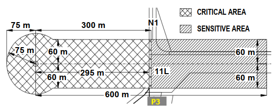
1.4.3.5 Critical and sensitive area of ILS CAT I - RWYs 11R, 29L, 11L, 29R and ILS CAT II - RWY 11R
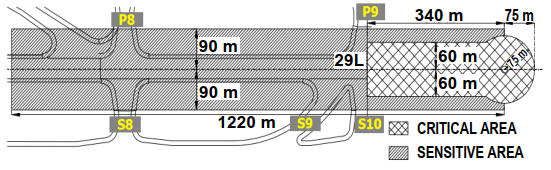
a. Critical and sensitive area of ILS CAT I - RWY 11R
 |
|---|
 |
|---|
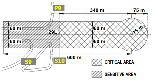
b. Critical and sensitive area of ILS CAT II - RWY 11R
 |
|---|
 |
|---|
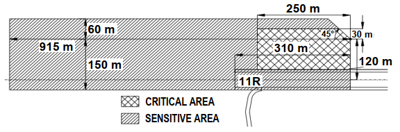
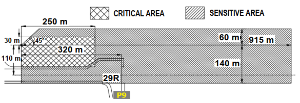
c. Critical and sensitive area of ILS CAT I - RWY 29L
 |
|---|
 |
|---|
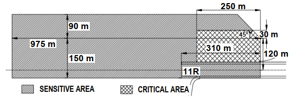
d. Critical and sensitive area of ILS CAT I - RWY 11L
 |
|---|
 |
|---|
e. Critical and sensitive area of ILS CAT I - RWY 29R
 |
|---|
 |
|---|
1.4.3.4 Aerodrome control movement procedure
- For departure aircraft:
- RWY 11R:
- Departing aircraft are allowed to taxi from apron via TWY S1B/S1C/S1D/S2A/S2B/S4/S6A/S7A via TWY S1 to CAT II onholding position ofRWY 11R; except for aircraft taxiing via TWY S1D, holding on taxilane EW in front of TWY S1D, aircraft is only allowed to taxi on TWY S1D when it is ready to takeoff and follow Noi Bai TWR clearance.
- Taxiing procedure via TWY S7 for taking offon RWY 11R (takeoff from theintersection of RWY 11R and TWY S7): Departing aircraft are allowed to taxifrom apron via TWY S1B/S1C/S1D/S2A/S2B/S4/S6A/S7A to TWY S1, TWY S7 to the RWY-holding position in front of RWY 11R.
- RWY 11L: Departing aircraft are allowed to taxifrom apron to TWY S2B/S2A/S1B/S4/S6A/S1C/S7A via TWY S1, TWY S7 to the RWY-holding position ofRWY 11R.
- RWY 29L/29R:
- Departing aircraft are allowed to taxi from apron via TWY S1B/S1C/S1D/S2A/S2B/S4/S6A/S7A via TWY S1, TWY S1A (for aircraft up to code C) to the RWY-holding position of RWY 29L/29R.
- Taxiing procedure via TWY S2 for taking off on RWY 29L/29R (take off from the intersection of RWY 29L/29R and TWY S2): Departing aircraft are allowed taxi from apron via TWY S1B/S1C/S1D/S2A/S2B/
S4/S6A/S7A via TWY S2 to the RWY-holding position of RWY 29L/29R.
Notes: Aircraft are not allowed to hold on the positions closer to RWY than the RWY-holding positions in front of RWY 11R (stop bar lights).
- For arrival aircraft:
- RWY 11R: After landing, aircraft vacate RWY via TWY S6/S4/S5A/S2/S1/S1A,then via TWY S2B/S2A/S1B/S4/S6A/S1C/ S7A/S1D into apron.
- RWY 11L: After landing, aircraft vacate RWY via S1/S2/S3/S5/P7, cross RWY 11R/29L into TWY S1/S1A/S2/S4/S5A, then via TWY S1/S1B/S1C/S1D/S2A/S2B/S4/S6A/S7A into apron.
- RWY 29R: After landing, aircraft vacates RWY via TWY S3/S5/P4/S7, cross RWY11R/29L into TWY S4/S5A/S6/S6B/S7, thenvia TWY S1/S1B/S1C/S1D/S2A/S2B/S4/S6A/S7A into apron.
- RWY 29L: After landing, aircraft vacate RWY via TWY S1/S4/S6/S6B/S7, cross RWY11R/29L into TWY S1/S1B/S1C/S1D/S1E/S2A/ S2B/S4/S6A/S7A into apron.
Notes: In case of construction on RWY, TWY and apron, the procedures mentioned above are not conducted, the current procedures will be applied during construction time.
1.4.4 Vehicles movement control
- Vehicles shall not enter RWY if landing aircraft has reached at 8 NM from touchdown;
- Vehicles are prohibited within manoeuvring area unless cleared by Noi Bai TWR;
- Vehicles are not allowed to hold on the positions closer to RWY than the holding position in front of RWY (stop bars lights).
1.5 Implementations in condition of low visibility
1.5.1 When weather condition decreases to LVP:
- Timely inform to pilots to suspend or do not apply ILS CAT II approach procedures;
- Ensure to broadcast the phrase "LOW VISIBILITY PROCEDURES IN OPERATION" on ATIS.
1.5.2 When appear "decrease" component in ILS CAT II operation standard:
- When ILS CAT II can not be applied, Noi Bai TWR must immediately inform to related aircraft, Noi Bai APP and apply appropriate flight operation procedures in accordance with regulations.
- Noi Bai APP/TWR unit reports to related aircraft and apply appropriate flight operation procedures in accordance with regulations.
- Timely inform to pilots about applying or do not applying ILS CAT II approach procedures.
1.6 Handling abnormal, emergency situations
- In abnormal/emergency situations, related units shall strictly co-ordinate with each other in handling situations, give priority to aircraft in urgency, select the most appropriate flight procedure and RWY to ensure the safety of flight as well as support ground services on request of pilots and in accordance with current regulations;
- Suspend other activities if necessary to give priority to aircraft in urgency.
1.7 Application condition of low visibility
LVP application will be implemented if there are requirements for flight operations, with standard weather conditions in item 1.3.2.2 of these procedures and the operational components in LVP at Noi Bai international airport meet minimum standards as follows:
1.7.1 For ILS/DME system runway 11R:
- Primary and secondary of Localizer (LLZ), Glidepath (GP), DME are normally operated;
- All of Localizer (LLZ), Glidepath (GP) and DME monitors are normally operated;
- There is no deviation between two of three devices (LLZ, GP, DME) can lead to device's warning;
- ILS/DME remote system is normally operated.
1.7.2 For lighting system runway 11R:
- Approach lighting systems:
- Within the range of 450 m (from RWY 11R THR): More than 95% of approach lighting systems are operated, and not any two consecutive lights are unserviceable;
- Outside the range of 450 m (from RWY 11R THR): More than 85% of approach lighting systems are operated, and not any two consecutive lights are unserviceable.
- RWY centre line lights, RWY edge lights, THR of RWY lights: More than 95% of lights are operated, and not any two consecutive lights are unserviceable ;
- Touchdown zone lights system: More than 90% of lights are operated, and any two consecutive lights are unserviceable;
- RWY end lights system: More than 70% of lights are operated, and any two consecutive lights are unserviceable;
- Stop bars lights system: More than 95% of lights are operated, and any two consecutive lights are unserviceable;
1.7.3 For RVR system, ceiling measuring ceilometers: RVR system and ceiling measuring ceilometers operate normally; RVR values at RWY 11R station, mid station and ceiling shall be directly indicated at working position of Noi Bai APP/TWR.
1.7.4 For power supply system: Electric power source for lighting system shall be provided by UPS - or by using electric generator as the primary source of power supply, using the grid supply as the secondary power supply.
1.7.5 For ILS critical/sensitive area: Personnel and vehicles are not allowed to operate within ILS critical and sensitive areas.
1.7.6 For airport emergency forces: Airport emergency services, facilities and equipments ensure meeting CAT 9 requirements for rescue and firefighting and are available to cope with urgency following the current emergency procedures.
Note: In case LVP is applied and weather conditions are good enough to operate ILS CAT I but ILS CAT II does not meet the standards (due to technical or facilities failure and maintenance team can immediately revert to normal operation), LVP application is continued.
2 Operational procedures for RNAV 1 SID/STAR
2.1 General
- In order to operate RNAV 1 SID/STAR procedures at Noi Bai Aerodrome, the aircraft navigation system shall meet ICAO RNAV 1 standard of accuracy based on GNSS infracstructure.
- Pilots, ATS personal and the related personnel are responsible for checking RAIM Prediction in accordance with operational procedure for RAIM Prediction Service.
- Aircraft operators/pilots who are not authorized to fly RNAV 1 procedures based on GNSS shall inform Air traffic controller (ATC) and expect to use conventional procedures in accordance with actual conditions.
- The transition routes have been established to connect RNAV 1 SID/STAR with the existing ATS routes.
2.2 Operational procedure
- Aircraft operators/pilots expecting to use RNAV 1 SID/STAR procedures at Noi Bai Aerodrome shall fill appropriate navigation capability indicators in flight plan, as follows:
- Insert R (PBN approved) into Item 10a.
- Inserting D1 (RNAV 1 all permitted sensors) or D2 (RNAV 1 GNSS) after PBN/.... in Item 18.
- Specify equipment to support each type of navigation capability in Item 18 and insert them into Item 10a (G, D, I for D1 or G for D2).
- Before implementation of flights, pilots must verify that the navigation database is updated to current time and verify that the aircraft position has been entered correctly. Pilots must confirm the entry and exit points on the ATS route assigned on initial clearance and any subsequent changes of route, ensuring the waypoints sequence depicted by their navigation system matches the route depicted on the appropriate chart(s) and their assigned route.
- Pilots must not fly a RNAV 1 SID/STAR unless it is retrievable by procedure from the on-board navigation database and conforms to the charted procedure (this procedure may subsequently be modified in response to ATC clearances). The manual entry, or creation of new waypoints by inserting latitude/longitude or rho/theta values is not permitted. Additionally, pilots must not change any RNAV 1 SID/STAR database waypoint type from a fly-by waypoint to a fly-over waypoint or vice versa.
- Conditions for applying RNAV 1 SID/STAR at Noi Bai: ATS surveillance is mandatory.
- ATC shall maintain monitoring aircraft when it conducts RNAV 1 SID/STAR. Pilots are expected to maintain route centrelines during all RNAV 1 operations unless authorized to deviate by ATC or under emergency conditions.
- Pilots shall comply with altitude assigned by ATC, as well as adhere to the altitude and speed restrictions depicted on the cleared RNAV 1 SID/STAR, unless there are other clearance by ATC.
- In case ATC assigns the aircraft not to conduct the expected procedure, the pilots should not modify the flight plan in the system until a clearance to rejoin the procedure is received or the ATC confirms a new procedure clearance.
During the operation of the RNAV 1 SID/STAR, ATC and pilots apply the standard phraseology specified in Doc 4444 PANS–ATM – ICAO, Procedures For Air Navigation Services – Air Traffic Management.
- Conventional SIDs/STARs and radar vectoring still applied to aircraft that are not approved for RNAV 1 and other aircraft depending on traffic situation.
2.3 For departing aircraft
- The procedures for departing aircraft include 2 main elements:
- SID; and
- Transition route if necessary.
- A transition route starts at the last point of SID to a position from which the aircraft will intercept the ATS route.
- Altitude restrictions are designed to establish the separation between departing aircraft and obstacles as well as arriving aircraft.
- ATC shall issue a clearance for departing aircraft including the following contents:
- Call sign;
- Clearance limit, normally destination aerodrome;
- SID and transition route if necessary;
- Route;
- Assigned flight level/altitude;
- SSR code; and
- Any other related and necessary instruction or information not contained in the SID description.
Notes:
In case a clearance provided SID is not assigned altitude/flight level, the pilots are not allowed to reach the altitude/flight level itself on the SID vertical profile. Pilots shall re-confirm with ATC to assign a specified altitude/flight level to ensure flight safety.
2.4 For arriving aircraft
- The procedures for arriving aircraft include 2 main elements:
- Transition route if necessary; and
- STAR.
- A transition route starts from a waypoint on the ATS route to the position that starts the STAR.
- Altitude restrictions are designed to establish the separation between arriving aircraft and obstacles as well as departing aircraft.
- Approach clearances shall be issued by ATC in accordance with actual operating conditions.
- ATC shall issue clearance for arriving aircraft including the following contents:
- Call sign;
- STAR and transition route if necessary;
- Runway-in-use;
- Cleared flight level/altitude; and
- Any other related and necessary instruction or information not contained in the STAR description.
Notes:
In case a clearance provided STAR is not assigned altitude/flight level, the pilots are not allowed to reduce the altitude/flight level itself on the STAR vertical profile. Pilots shall re-confirm with ATC to assign a specified altitude/flight level to ensure flight safety.
2.5 Contingency procedure
2.5.1 Aircraft is unable to comply with RNAV 1 requirements
If aircraft is unable to comply with RNAV 1 requirements, pilots shall inform ATC immediately and expect to be used the conventional procedure in accordance with actual conditions.
2.5.2 Aircraft degrade the RNAV capability or failure of GNSS signal
When the aircraft degrade the RNAV 1 capability or fail in GNSS signal, which leads to the inability to comply with the requirements of RNAV 1, pilots must advise ATC immediately and expect to be used the conventional procedure in accordance with actual conditions.
2.5.3 Aircraft experience bad weather
When an aircraft flying on RNAV 1 procedures encounters bad weather which is likely to impact the aircraft’s adherence to the cleared flight procedures, pilots will notify ATC and request a revised clearance. ATC clearance "Direct to" will be used for aircraft to avoid bad weather where applicable. In case bad weather area affects important points of RNAV 1 procedures, radar vector shall be applied by ATC for all aircraft.
2.5.4 Radio communications failure procedure
In case of a radio communication failure, the pilots are expected to proceed the following procedures:
- Set transponder to Mode A/C, code 7600;
- Arriving aircraft continue flying on the assigned STAR procedure, complying with the altitude and speed restrictions and at the end of the STAR make appropriate approach procedures;
- Departing aircraft continue flying on the assigned SID procedure, complying with the altitude and speed restrictions, climb to cruising level as mentioned in the current flight plan.
2.5.5 ATS surveillance failure procedure
- ATC implement processing method according to the operating procedure specified in the operations manual of ATS unit.
- ATC expect to apply non-radar procedural control for all aircraft until ATS surveillance system resumes normal operation.
2.5.6 Procedure for changing runway-in-use
- ATC shall assign time to conduct the change of the runway-in-use, determine aircraft sequence corresponding to the runway-in-use to notify and issue the assigned clearance for RNAV 1 SID/STAR procedures which are suitable for the pilots.
- In case of necessity, ATS surveillance vectoring may be used by ATC to deal with complicated situations.
3 RNAV 1 SID/STAR waypoints
NR | Wayoints | Coordinates (WGS-84) | Remark |
|---|---|---|---|
| 1 | RW11L | 211330.95N 1054733.25E | THR |
| 2 | RW11R | 211328.91N 1054710.85E | THR |
| 3 | RW29L | 211252.52N 1054916.77E | THR |
| 4 | RW29R | 211300.28N 1054919.32E | THR |
| 5 | BANCO | 212954.2N 1055758.5E | |
| 6 | BISON | 202559.9N 1053829.8E | |
| 7 | BQ | 211254.0N 1040217.0E | NAVAID |
| 8 | KHARO | 210046.8N 1051422.3E | |
| 9 | BUNBO | 214226.1N 1061948.1E | |
| 10 | DALAI | 212208.1N 1053901.2E | |
| 11 | DENMO | 220229.8N 1062452.2E | |
| 12 | DIHAI | 214954.0N 1060748.8E | |
| 13 | DILEN | 220635.4N 1052812.6E | |
| 14 | DONMO | 211037.7N 1053515.4E | |
| 15 | FINAM | 203307.1N 1055936.2E | |
| 16 | HAKAO | 214355.0N 1061610.0E | |
| 17 | HOBIN | 204100.4N 1053820.2E | |
| 18 | HUVAN | 211230.0N 1050641.0E | |
| 19 | JULUN | 214518.7N 1052402.5E | |
| 20 | KUNHI | 211732.2N 1055457.3E | |
| 21 | LENNU | 212019.0N 1050728.2E | |
| 22 | LIMIN | 213539.3N 1060604.3E | |
| 23 | MC | 204941.0N 1044201.0E | NAVAID |
| 24 | MIMON | 205032.6N 1053815.7E | |
| 25 | MUCHI | 205643.5N 1050252.8E | |
| 26 | NAH | 202314.0N 1060704.0E | NAVAID |
| 27 | NAKHA | 215800.0N 1062936.0E | |
| 28 | NUCOC | 213321.9N 1054533.9E | |
| 29 | SONTA | 210121.7N 1053810.5E | |
| 30 | SUDON | 212302.2N 1054901.2E | |
| 31 | TAMDA | 214922.3N 1053055.8E | |
| 32 | THOLA | 214421.6N 1054152.6E | |
| 33 | TINLY | 203436.1N 1060458.0E | |
| 34 | XARIS | 210105.2N 1052638.6E | |
| 35 | XUNBI | 210445.7N 1050736.5E | |
| 36 | NB110 | 211002.7N 1055932.9E | |
| 37 | NB111 | 205734.1N 1055807.5E | |
| 38 | NB112 | 211905.0N 1060232.0E | |
| 39 | NB113 | 212507.7N 1054151.5E | |
| 40 | NB114 | 205305.7N 1054527.6E | |
| 41 | NB290 | 211815.4N 1053036.2E | |
| 42 | NB291 | 212653.3N 1053326.7E | |
| 43 | NB292 | 210937.5N 1052745.8E | |
| 44 | NB293 | 210555.1N 1053226.3E | |
| 45 | NB360 | 211635.6N 1053653.0E | |
| 46 | NB361 | 211622.7N 1053708.2E | |
| 47 | NB362 | 211742.2N 1053231.8E | |
| 48 | NB363 | 211901.6N 1052755.3E | |
| 49 | NB364 | 212020.8N 1052318.7E | |
| 50 | NB365 | 212139.9N 1051842.1E | |
| 51 | NB366 | 211554.3N 1051649.5E | |
| 52 | NB367 | 211435.2N 1052126.3E | |
| 53 | NB368 | 211316.1N 1052602.7E | |
| 54 | NB369 | 211157.0N 1053039.1E | |
| 55 | NB371 | 210050.2N 1051630.4E | |
| 56 | NB372 | 205102.3N 1051930.2E | |
| 57 | NB373 | 204339.2N 1052729.8E | |
| 58 | NB374 | 205001.2N 1051740.0E | |
| 59 | NB375 | 204154.5N 1052626.7E | |
| 60 | NB376 | 203900.6N 1053821.2E | |
| 61 | NB377 | 212725.9N 1052034.6E | |
| 62 | NB378 | 212606.6N 1052511.3E | |
| 63 | NB379 | 212447.2N 1052948.0E | |
| 64 | NB380 | 212327.7N 1053424.6E | |
| 65 | NB381 | 214226.9N 1054231.1E | |
| 66 | NB382 | 214316.9N 1055109.1E | |
| 67 | NB383 | 214053.4N 1055926.7E | |
| 68 | NB384 | 214516.5N 1055121.7E | |
| 69 | NB385 | 214238.9N 1060028.4E | |
| 70 | NB386 | 213653.8N 1060745.2E | |
| 71 | NB451 | 210955.0N 1055930.3E | |
| 72 | NB452 | 210834.9N 1060406.3E | |
| 73 | NB453 | 210714.6N 1060842.1E | |
| 74 | NB454 | 210554.3N 1061317.9E | |
| 75 | NB455 | 210433.8N 1061753.6E | |
| 76 | NB456 | 211002.4N 1055932.9E | |
| 77 | NB462 | 211540.1N 1060124.3E | |
| 78 | NB463 | 211420.0N 1060600.1E | |
| 79 | NB464 | 211259.9N 1061036.2E | |
| 80 | NB465 | 211139.6N 1061512.2E | |
| 81 | NB466 | 211019.2N 1061948.1E | |
| 82 | BIVIM | 193034.0N 1060628.0E | |
| 83 | TOSCA | 194827.0N 1055729.0E | |
| 84 | NB501 | 194438.0N 1054312.0E | |
| 85 | NB502 | 194545.0N 1052720.0E | |
| 86 | NB503 | 195243.0N 1051203.0E |
VVNB AD 2.23 ADDITIONAL INFORMATION
1. Birds and wildlife activitiesin the vicinity of airports affect to aerodrome
Birds species | Number of birds, heightband, density, operating period, roost and feeding position | Daily movement, across the aerodrome | Safety risk level |
| 1 | 2 | 3 | 4 |
Hawk, Falcon | |||
+ Number of birds: A few birds. + Heightband (AGL): 20–30 M AGL. + Operating period: By day. + Roost and feeding position: The East lake area. | Yes | High | |
Quail | |||
+ Number of birds: A few dozen of birds. + Heightband (AGL): On the ground. + Operating period: By day. + Roost and feeding position: The East lake area. | Yes | Low | |
Owl | |||
+ Number of birds: A few birds. + Heightband (AGL): 20–30 M AGL. + Operating period: By night. + Roost position: The apron NR 15. + Feeding position: The East lake area. | Yes | High | |
Field sparrow | |||
+ Number of birds: A few dozen of birds. + Heightband (AGL): 15–20 M AGL. + Operating Period: By day. + Roost position: The North of RWY 11L/29R. + Feeding position: The East lake area. | Yes | Low |
2. Operational procedure of holding position S7 - RWY 11L
Holding point S7 is used for RWY 11L when:
- There is no aircraft taking off and landing on RWY 11R/29L;
- Aircraft use ILS x, ILS y, ILS z approach procedures for RWY 11L in case of GP unserviceable;
- Aircraft use VOR y, VOR z, NDB approach procedures for RWY 11L and aircraft use visual approach procedure.
Holding point S7 is not used for RWY 11L (holding point S4 or S6 is used instead, if necessary) when:
- There is aircraft taking off and landing on RWY 11R/29L;
- Aircraft use ILS x, ILS y, ILS z approach procedures for RWY 11L at final approach fix (intercept GP) in case of GP serviceable.
3 Table of friction coefficients
RWY 11R/29L | Measured length (M) | Friction coefficients | ||
|---|---|---|---|---|
Measured position from RCL (3 M) | Measured position from RCL (6 M) | Measured position from RCL (9 M) | ||
| 11R | 3 300 | 0.67 | 0.68 | 0.65 |
| 29L | 3 300 | 0.66 | 0.66 | 0.64 |
RWY 11L/29R | Measured length (M) | Friction coefficients | ||
|---|---|---|---|---|
Measured position from RCL (3 M) | Measured position from RCL (6 M) | Measured position from RCL (9 M) | ||
| 11L | 2 701 | 0.77 | 0.75 | 0.74 |
| 29R | 2 701 | 0.74 | 0.77 | 0.75 |
4 HOT SPOTS
HOT SPOT NR | Position |
|---|---|
| HS 1 | - Position: The - Pilots must increase observations, hold |
| HS 2 | - Position: TWY - Pilots must increase observations when aircraft enter or cross TWY S6 and the |
| HS 3 | - Position: The - Pilots must read-back ATC clearances and increase observations for light signals, marker boards and instructions in order to taxi in accordance with the clearances. - Pilots |
5 Operation of two parallel RWYs
5.1 Usage of two parallel RWYs
- Two parallel RWYs 11R/29L and 11L/29R at Noi Bai international airport are operated dependently and considered as one RWY for flight operation.
- At the same time, only one RWY direction is used for take-off/landing.
- In case of rain-storm (but still above LVP condition) RWY 11R is priority to use for landing and RWY 11L is used for take-off with the best facilities and actual operational conditions.
- When RWY 29 is used for take-off/landing, RWY 29L is priority to use for landing, RWY 29R is used for take-off.
- In case of having VIP flights: RWY with the best facilities and actual operational conditions is priority to use.
- The usage of RWY for flight calibration of navigation aids, instrument procedures and for familiarisation flights has to follow the flight permission, ATS flight plan which have been approved by appropriate authorities.
- Exit TWYs shall be used to facilitate arriving aircraft to quickly vacate sensitive area of ILS/LLZ; aircraft is not allowed to hold on holding positions in sensitive area.
These operational procedures do not be applied in the emergency, urgency and necessary condition to ensure the safety, regularity of the flight operation.
5.2 Operation procedures of two RWYs
5.2.1 Operational option 1: RWY 11L is used for landing, RWY 11R is used for take-off
5.2.1.1 ATCsDeparting are only allowed to issue take-off clearance for aircraft which is holding on RWY 11R (pilots are ready for take-off) is only allowed to take-off when landing aircraft has landed normally on RWY 11L; or not less than the values in the following conditionsvalues:
a. Without ATS surveillance: Applied minimum time wake turbulence separation:
- 2 minutes: If medium aircraft (landing) behind heavy aircraft (take-off);
) - 3 minutes: If light aircraft (landing) behind heavy or medium aircraft (take-off).
b. Under ATS surveillance: ApplyingApplied the minimum distance wake turbulence separation.:
Wake turbulence categoryWake turbulence category | Distance of landing ACFT from RWY THR 11LDistance of landing ACFT from RWY THR | |
Arriving aircraft | Departing aircraft | |
Heavy | Heavy | 7.4 |
Medium | 5.5 KM (3 NM) | 9, 3 KM (5 NM) |
Light | ||
Medium | Heavy | 9.3 |
Medium | 5.5 KM (3 NM) | |
Light | 9, 3 KM (5 NM) | |
Light | Heavy | 11.1 KM (6 NM) |
Medium | Heavy, medium | 9.3 |
Light | 5.5 | |
Notes: The aircraft take off first, the aircraft land later.
In8 caseNM theis applied between preceding take-off aircraft is aircraft A380 orand equivalent above, and the following landing aircraft shall apply the minimum separation 8 NM.
The figure illustrates some cases:
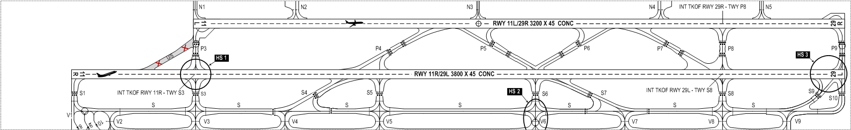 |
|---|
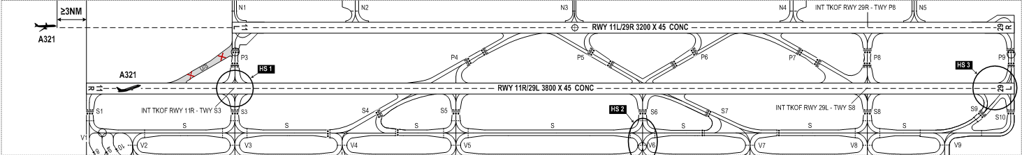 |
|---|
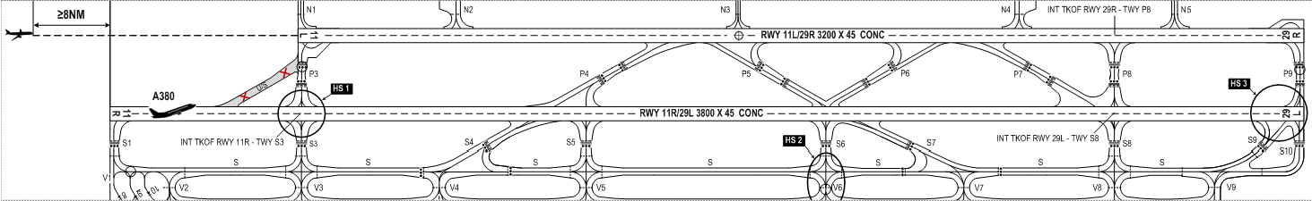 |
|---|
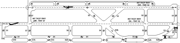 |
|---|
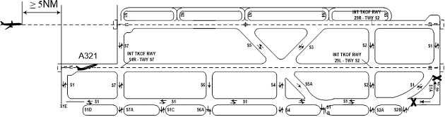 |
|---|
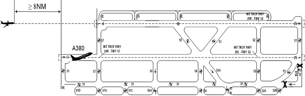 |
|---|
5.2.1.2 WhenIn usingcase the intersection of RWY 11R and TWY S3 for taketaking-off: Aircraft atfrom the intersection ofbetween RWY 11R and TWY S3S7: Departing aircraft starts runningrolling for take-off whenwhile at the same time another landing aircraft is approaching at 35 NM or more on the final approach track of RWY 11L. . .
  |
|---|
5.2.2 Operational option 2: RWY 11L is used for take-off aircraft, RWY 11R is used for landing aircraft
5a.2.2.1Departing The aircraft is not allowed to hold on TWY P3S7 (between two RWYs) while arriving aircraft is approaching to land on RWY 11R.
5b.2.2.2 Aircraft is not allowed to cross RWY 11R when:
- There is another aircraft received ATC's clearance to land on RWY 11R, or
- There is another aircraft is approaching to land RWY 11R with the distance less than 6 NM from THR of RWY 11R under ATS surveillance or less than 3 minutes compared to estimated landing time in case of non using ATS surveillance;
5c.2.2.3Departing ATCs are only allowed to issue take-off clearance for aircraft which is holding on RWY 11L (pilots are ready for take-off) is only allowed to take-off when landing aircraft has landed normally on RWY 11R;
or not less than the valuesspecified in theitems followinga, b conditions:of 7.2.1.1.
or not less than the values
a. Without ATS surveillance: Applied minimum time wake turbulence separation:
- 2 minutes: If medium aircraft (landing) behind heavy aircraft (take-off);
- 3 minutes: If light aircraft (landing) behind heavy or medium aircraft (take-off).
b. Under ATS surveillance: Applying the minimum distance wake turbulence separation.
Wake turbulence category | Distance of landing ACFT from THR 11R | |
Arriving aircraft | Departing aircraft | |
Heavy | Heavy | 7.4 KM (4 NM) |
Medium | 5.5 KM (3 NM) | |
Light | ||
Medium | Heavy | 9.3 KM (5 NM) |
Medium | 5.5 KM (3 NM) | |
Light | ||
Light | Heavy | 11.1 KM (6 NM) |
Medium | 9.3 KM (5 NM) | |
Light | 5.5 KM (3 NM) | |
Notes: The aircraft take off first, the aircraft land later.
In case the preceding take-off aircraft is aircraft A380 or equivalent above, the following landing aircraft shall apply the minimum separation 8 NM.
The figure illustrates some cases:
  |
|---|
  |
|---|
  |
|---|
5.2.3 Operational option 3: RWY 29R is used for landing aircraft, RWY 29L is used for take-off aircraft
5a.2.3.1Departing ATCs are only allowed to issue take-off clearance for aircraft which is holding on RWY 29L (pilots are ready for take-off) is only allowed to take-off when landing aircraft has landed normally on RWY 29R; or not laterless than the timevalues specified in theitems followinga, b conditions:of 7.2.1.1.
a. Without ATS surveillance: Applied minimum time wake turbulence separation:
- 2 minutes: If medium aircraft (landing) behind heavy aircraft (take-off);
- 3 minutes: If light aircraft (landing) behind heavy or medium aircraft (take-off).
b. Under ATS surveillance: Applying the minimum distance wake turbulence separation.
Wake turbulence category | Distance of landing ACFT from THR 29R | |
Arriving aircraft | Departing aircraft | |
Heavy | Heavy | 7.4 KM (4 NM) |
Medium | 5.5 KM (3 NM) | |
Light | ||
Medium | Heavy | 9.3 KM (5 NM) |
Medium | 5.5 KM (3 NM) | |
Light | ||
Light | Heavy | 11.1 KM (6 NM) |
Medium | 9.3 KM (5 NM) | |
Light | 5.5 KM (3 NM) | |
Notes: The aircraft take off first, the aircraft land later.
In case the preceding take-off aircraft is aircraft A380 or equivalent above, the following landing aircraft shall apply the minimum separation 8 NM.
The figure illustrates some cases:
  |
|---|
 |
|---|
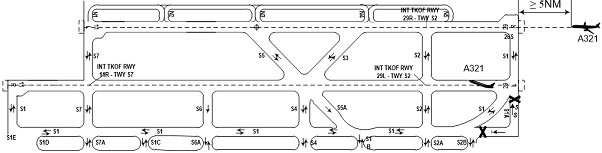 |
|---|
  |
|---|
5b.2.3.2In Whencase using the intersection of RWY 29L and TWY S8 for taketaking-off: Aircraft atfrom the intersection between RWY 29L and TWY S8S2: Departing aircraft starts runningrolling for take-off whenwhile at the same time another landing aircraft is approaching at 35 NM or more on the final approach track of RWY 29R.
  |
|---|
5.2.4 Operational option 4: RWY 29R is used for take-off aircraft, RWY 29L is used for landing aircraft
5a.2.4.1 Aircraft is not allowed to cross RWY 29L when:
- There is another aircraft received ATC's clearance to land on RWY 29L, or
- There is another aircraft approaching to land RWY 29L with the distance less than 6 NM from THR of RWY 29L under ATS surveillance or less than 3 minutes compared to estimated landing time in case of non using ATS surveillance.
5b.2.4.2Departing ATCs are only allowed to issue take-off clearance for aircraft which is holding on RWY 29R (pilots are ready for take-off) is only allowed to take-off when landing aircraft has landed normally on RWY 29L; or not laterless than the timevalues specified in theitems followinga, b conditions:of 7.2.1.1.
a. Without ATS surveillance: Applied minimum time wake turbulence separation:
- 2 minutes: If medium aircraft (landing) behind heavy aircraft (take-off);
- 3 minutes: If light aircraft (landing) behind heavy or medium aircraft (take-off).
b. Under ATS surveillance: Applying the minimum distance wake turbulence separation.
Wake turbulence category | Distance of landing ACFT from THR 29L | |
Arriving aircraft | Departing aircraft | |
Heavy | Heavy | 7.4 KM (4 NM) |
Medium | 5.5 KM (3 NM) | |
Light | ||
Medium | Heavy | 9.3 KM (5 NM) |
Medium | 5.5 KM (3 NM) | |
Light | ||
Light | Heavy | 11.1 KM (6 NM) |
Medium | 9.3 KM (5 NM) | |
Light | 5.5 KM (3 NM) | |
Notes: The aircraft take off first, the aircraft land later.
In case the preceding take-off aircraft is aircraft A380 or equivalent above, the following landing aircraft shall apply the minimum separation 8 NM.
The figure illustrates some cases:
  |
|---|
  |
|---|
  |
|---|
5c.2.4.3In Whencase usingof thetaking-off from intersection ofbetween RWY 29R and TWY P8 for take-offS2:
- Aircraft is not allowed to hold on TWY P8
S2(between two RWYs) whenwhilethe otheranotherlanding aircraft is approachingto landon RWY 29L; - Aircraft
Inatcasetheoftaking off fromintersection ofbetweenRWY 29R and TWY P8S2: Aircraftstarts runningrollingfor take-off whenwhileat the same time another landing aircraft is approaching at 35NM or more on the final approach track of RWY 29L.
  |
|---|
5.2.5 Operational option 5: Both RWYs 11L and 11R are used for take-off aircraft
- ATCs
Departingdoaircraftisnot allow aircraftallowedto line-up two RWYs at the same time for take-off in order to avoid mistaking take-off clearance from ATC; - This operation option is limited.
5.2.6 Operational option 6: Both RWYs 11L and 11R are used for landing aircraft
- Using as one RWY;
- This operation option is limited due to no capability of standby.
5.2.7 Operational option 7: Both RWYs 29L and 29R are used for take-off aircraft
- ATCs
Departingdoaircraftisnot allow aircraftallowedto line-up two RWYs at the same time to take off in order to avoid mistaking take-off clearance from ATC; - This operation option is limited.
57.2.8 Operational option 8: Both RWYs 29L and 29R are used for landing aircraft
- Using as one RWY;
- This operation option is limited due to no capability of standby.
Notes:
- Pilots shall fully understand operational procedures of two parallel RWYs specified as above;
- Pilots are requested to comply with ATC's clearances/instructions strictly and timely; expedite vacate RWY or rolling to take-off after receiving take-off clearance;
- Aircraft must be held on the correct holding position on the TWYs between two RWYs when requested by ATC;
- Before landing, lining up or crossing RWYs, pilots must pay attention and concentrate on observing and only conducting actions after adequately receiving and reading back ATC's clearance;
- For ready take-off aircraft, pilots shall ensure that aircraft start rolling for take-off within 30 seconds from receiving take off clearance; For landing aircraft, aircraft expedite vacating RWYs within 45 seconds after deceleration. If aircraft is unable to take-off/decelerate and vacate RWY at the time mentioned above, pilots shall inform Noi Bai TWR.
Pilots shall fully understand and implement standard operational procedures (SOP) and these operational procedures; focus on observing, strictly complying and implementing ATC clearances fully and in a timely manner to reduce RWY occupation time.
For departure aircraft:
- Pilots shall be ready for take-off; ensure that aircraft shall be held on the assigned holding point as requested by ATC.
- Expedite to carry out the line up RWY and take-off clearances
Notes: Line up RWY clearance is not take-off clearance. - Pilots shall ensure that aircraft start rolling for take-off within 30 seconds after receiving take-off clearance (if the aircraft is unable to do so, pilots shall inform Noi Bai TWR immediately).
For landing aircraft: Pilots expedite to vacate RWYs (ensure that the tail of the aircraft vacating the holding point marking) within 60 seconds after deceleration (if the aircraft is unable to do so, pilots shall inform Noi Bai TWR immediately).
6 Arrival, departure manager system (AMAN/DMAN)
6.1 Purpose
The AMAN/DMAN is implemented to manage, sequence arrival and departure flights at Noi Bai international Airport, improve the capacity of airspace and aerodromes operations within Ha Noi FIR in particular and in Viet Nam in general.
6.2 Scope
Automated ATM system, related equipment systems, the air navigation services (ANS) units: Ha Noi ACC and Noi Bai APP/TWR and the other ANS units relating to ANS provisions of the Northern Region Air Traffic Services Company.
6.3 Subject of application
Viet Nam Air Traffic Management Corporation: Northern Region Air Traffic Services, Viet Nam Aeronautical Information Centre and the others related departments/units.
The others departments/units related to the implementation of AMAN/DMAN at Noi Bai International Airport: Noi Bai International Airport; the Airlines to/from Noi Bai International Airport; the Ground Services Companies at Noi Bai International Airport.
6.4 AMAN system
6.4.1 AMAN processing areas
- Base on flight plan data, surveillance data and related meteorological data, AMAN calculates, arranges and provides the shortest flight trajectory for each flight. During flight landing process calculation, AMAN establishes 3 processing areas, in which flights are calculated, sequenced and can be changed the order to match the actual air traffic situation. Flights are closer to the destination airport will expect less change in arriving sequence. These 3 processing areas of AMAN include:
+ The “free part” is the area where AMAN will sequence arrival flights based on flight plans. STA and arrival sequence are constantly updated based on surveillance data and actual flight trajectory, therefore, arriving sequence can be automatically changed due to calculations of the system.
+ The “frozen part” is the area where AMAN will not automatically insert new flights or change the order of flights to sustain landing sequence . Under unusual circumstances, ATC may change landing sequence to handle situations.
+ The “final part” is the area after the aircraft have passed the final approach fix (FAF). AMAN updates the aircraft's STA for the last time at the FAF. In this area, AMAN will not change the sequence and flight’s STA.
- 10 minutes before the aircraft enters Ha Noi FIR, the AMAN/DMAN system will start calculating, sequencing and displaying the flight's STA on AMAN/DMAN screen. STA is continuously updated by the system according to the actual trajectory of the flight.
6.4.2 Recommendations by AMAN
a. Holding advice:
- When AMAN calculates and achieves the optimal sequence of arrivals, it may recommend that some flights have to wait at the designated holding areas.
- In case the speed control is not achieved and the flight must be brought into the holding pattern, AMAN will monitor the flight and reduce the remained holding time of flight when a new trajectory is calculated.
b. Speed advice:
To achieve the desired sequence, during the calculation, AMAN can make recommendations to increase/reduce speed of a certain flight. Recommendations are given in Mach number (if the aircraft is in an en-route phase) or CAS (if the aircraft is in a descent phase) and AMAN assumes that there is no difference between Indicated Airspeed (IAS) and Calibrated Airspeed (CAS).
6.5 DMAN system
Operational principles
- Based on flight plan data (EOBT) and wake turbulence separation standards, aircraft parking positions, taxiway configuration, runway, runway operating limitations, priority level of the flight ... DMAN calculates to provide departure sequence of aircrafts with two estimated times for the flight: Target take-off time (TTOT) and Target startup approves time (TSAT).
- Besides, based on the principle of grouping arrival aerodromes by distance, aircraft turbulence category and actual air traffic situation, ATC can adjust/change the sequence of departing aircrafts, ensure the safety, order and efficiency of flight operations at Noi Bai International Airport.
- 60 minutes before the EOBT of the flight, the AMAN/DMAN system will calculate and display the TSAT and TTOT, sequences of the flights on the AMAN/DMAN system and will be shared with related departments/units through the AMAN/DMAN sharing screen.
- Changing EOBT of a flight will result in the system recalculating the TSAT and changing the flight’s departure sequence.
6.6 Flight planning of airlines
6.6.1 For arriving flight
- Arrivals shall be calculated by AMAN and be arranged sequence on the Timeline when meeting the following requirements:
+ Field 15 of the flight plan shall be fully filled, especially the shortest arrival procedure;
+ Arrival procedure of flight shall be complied with RWY using mode established at AMAN/DMAN terminal at operating time (assigned by Watch-supervisor of Noi Bai TWR).
6.6.2 For departing flight
- Departures shall be calculated by DMAN and be arranged sequence on the Timeline when meeting the following requirements:
+ Field 15 of the flight plan shall be fully filled, especially departure procedure;
+ SID of flight shall be complied with RWY using mode established at AMAN/DMAN terminal at operating time (assigned by Watch-supervisor of Noi Bai TWR).
6.7 Coordination procedure processing data arrival and departure manager system (AMAN/DMAN)
This procedure is applied to flights arriving to and departing from Noi Bai International Airport when apply AMAN/DMAN (except for VIP flights, special flights, flights with technical problems and emergency flight which are prioritised in accordance with current regulations).
6.7.1 For arriving flight
- Data of the designated times for Scheduled Time of Arrival (STA), Actual Time of Arrival (ATA) of the flight will be calculated by the AMAN/DMAN system and displayed on the system 10 minutes before the arriving flight enters Ha Noi FIR.
- Based on the STA, related units must ensure that the aircraft stand/passenger boarding bridge, facilities and vehicles are ready to serve the flight at least 5 minutes before the time the aircraft taxi into stand/passenger boarding bridge.
- ATC ensures to coordinate and unify with pilot to effectively comply with AMAN's recommendations for flights such as increase/reduce speed, using the holding pattern, extend or shorten the track, etc., depending on the air traffic situation.
a. Responsibility of pilot
- Co-operating and complying with the ATCs' clearances to follow AMAN's recommendations for flights such as increase/reduce speed, using the holding pattern, extend or shorten the track ... depending on the air traffic situation. Early notifying ATC if pilot is unable to comply with an alternative plan.
- Comply with the regulations on speed control in the air and on the movement area:
+ Air speed control:
- All aircrafts using SID/STAR RNAV 1 shall follow the speed restrictions specified in the flight procedures (published in AIP Viet Nam). If unable to follow the speed restrictions, pilot shall inform ATC immediately and report expected speed.
- Speed restriction within Noi Bai TMA are as follows:
- Aircraft under FL 100: Maximum speed 250 kt (IAS).
- Arrival aircraft is 12 NM (track mile) from touchdown: Maximum speed 200 kt (IAS).
- Arrival aircraft is 5 NM (track mile) from touchdown: Maximum speed 160 kt (IAS).
+ Speed control on movement area:
- Aircraft taxiing speed into stand equipped with visual docking guidance system (VDGS): As published in AIPViet Nam, Item VVNB AD 2.9.
- Aircraft taxiing speed at the movement area:
- RWY area: Not exceed 40 kts;
- TWY area: Not exceed 30 kts when the aircraft is performing a straight taxi;
- Apron area: Not exceed 15 kts before approaching the last turn to the parking; not exceed 10 kts when turning in the last turn to the parking (with marshaller), then reduce speed to approach the stand, stop right at the stop line. Pilots must strictly follow the marshaller’ instructions, including the signal requesting to reduce speed (if any).
- When taxiing aircraft makes a turn of 90° or more: Not exceed 10 kts.
- In low visibility operation (LVO): Not exceed 10 kts.
- In order to reduce RWY occupancy time and expedite the air traffic flow, pilots must immediately perform the RWY vacating clearance and ensure that the tail of the aircraft vacate the relevant holding position within the time not exceeding 60 seconds after rolling out; immediately notify Noi Bai TWR if unable to perform.
b. Flight plan procedure of airlines
Field 15 of the flight plan shall be fully filled, especially the shortest arrival procedure (STAR) complied with RWY operating mode at Noi Bai International Airport.
+ Arrival procedures when using RWY 11L/R include: BISON 1L/1R, HAKAO 1N/1R, HUVAN 1N/1R, MUCHI 1L/1R, TAMDA 1N/1R.
+ Arrival procedures when using RWY 29L include: BISON 1P, HAKAO 1P, HUVAN 1P, MUCHI 1P, TAMDA 1P.
6.7.2 For departing flight (chart the coordination procedures process the implementation of AMAN/DMAN system as mentioned in Item c. below)
- 60 minutes before the Estimated Off-Block Time (EOBT) of flight, DMAN will calculate and display the Target Start-up Approval Time (TSAT) and Target Take-of Time (TTOT) in the system. After exploiting on the AMAN/DMAN sharing screen, airlines (domestic and international), Viet Nam Airport Ground Services (VIAGS), Ha Noi Ground Services (HGS) are responsible to inform the TSAT, TTOT of the flight to the pilot.
- After the TSAT of flight is displayed on the AMAN/DMANsharing screen, the airline's representative (domestic/international) is responsible to inform ATC operating AMAN/DMAN the updated/revised EOBT of the flight in case there is a deviation of 5 minutes or more. The change of EOBT shall be limited (not more than 3 times) to ensure the stability of the TTOT calculation process.
- ATC will notify the pilot if there is a change the TSAT of the flight.
a. Responsibilities of the pilot:
- At least 5 minutes before the EOBT, pilots shall ensure to contact ATC - Clearance delivery position (119.25 MHz) for ATC clearance.
- Receive information about TSAT, TTOT of flight from airline’s representative (domestic/international); initiatively co-operate to implement the flight preparation procedures to ensure the compliance with the TSAT and TTOT of flight.
- ± 5 minutes of TSAT, the pilot contacts GCU Noi Bai (121.9 MHz) to request for startup/pushback (after receiving the ATC clearance). If more than 5 minutes after receiving the clearance, the aircraft does not startup/pushback due to not being ready, the TSAT of flight will be cancelled (except in case of aircraft condition on the apron). Pilots shall notify ATC the reason and the next plan. ATC will inform new TSAT of the flight.
- In order to reduce RWY occupancy time and expedite the air traffic flow, the pilots must be prompt to line up RWY, rolling for take-off within 30 seconds since receiving take-off clearance. Immediately notify Noi Bai TWR if unable to perform.
- Comply with regulations on speed control on the movement area as mentioned in Item a. part 8.7.1.
b. Flight plan procedure of airlines
- Field 15 of the flight plan shall be fully filled, especially departure procedure (SID) complied with RWY operating mode at Noi Bai International Airport.
+ Departure procedures when using RWY 11L/R include: JULUN 1A/1B, BUNBO 1A/1B, TINLY 1A/1B, MUCHI 1A/1B, HUVAN 1D/1E.
+ Departure procedures when using RWY 29L/R include: JULUN 1C/1D, DIHAI 1A/1B, FINAM 1A/1B, XUNBI 1A/1B, LENNU 1A/1B.
Note: In case of changing the submitted flight plan:
- If a flight with submitted filled flight plan may be delayed 30 minutes or more than the EOBT filled in the flight plan. The pilot/ airline’s representative /ARO shall immediately notify TWR Noi Bai or the Air Traffic Services Reporting Office (ARO) at Noi Bai International Airport to issue a DELAY message as regulated.
- If the flight is delayed more than 60 minutes of the EOBT filled in the flight plan, the pilots/airline’s representative/ARO shall revise the flight plan or submit a new flight plan.
c. Chart the coordination procedures process the implementation of AMAN/DMAN system
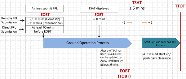 |
|---|
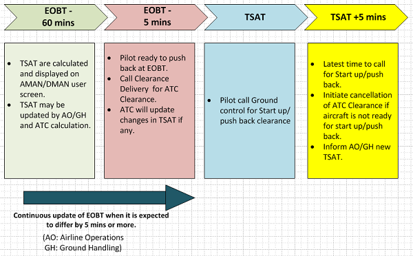 |
|---|
7 Place safety cones around the aircraft
In case of need to mark stop line, safety cones will be placed on the both sides of the stop line, 2 m to 3 m from the centre line of the taxilane to stand before aircraft taxi into stand.
VVNB AD 2.24 CHARTS RELATED TO NOI BAI AERODROME
VVNB AD 2.24-1: Aerodrome Chart – ICAO
VVNB AD 2.24-1: Aerodrome Chart – ICAO
VVNB AD 2.24-2: AD Operating Minima
VVNB AD 2.24-2a: AD Operational Minima
VVNB AD 2.24-3: Aircraft Parking/Docking Chart – ICAO
VVNB AD 2.24-3a: The INS coordinates and elevation for ACFT Stands
VVNB AD 2.24-3b: The INS coordinates and elevation for ACFT Stands (cont.)
VVNB AD 2.24-3c: The INS coordinates and elevation for ACFT Stands (cont.)
VVNB AD 2.24-3d: The INS coordinates and elevation for ACFT Stands (cont.)
VVNB AD 2.24-4: Aerodrome Ground Movement Chart – ICAO
VVNB AD 2.24-3: Aircraft Parking/Docking Chart – ICAO
VVNB AD 2.24-3a: The INS coordinates and elevation for ACFT Stands
VVNB AD 2.24-3b: The INS coordinates and elevation for ACFT Stands (cont.)
VVNB AD 2.24-3c: The INS coordinates and elevation for ACFT Stands (cont.)
VVNB AD 2.24-4: Aerodrome Ground Movement Chart – ICAO
VVNB AD 2.24-5: Aerodrome Obstacle Chart – ICAO – RWY 11R/29L
VVNB AD 2.24-5a: Aerodrome Obstacle Chart – ICAO – RWY 11L/29R
VVNB AD 2.24-5b: Aerodrome Obstacle Chart – ICAO – Type B
VVNB AD 2.24-6: Precision Approach Terrain Chart - ICAO
VVNB AD 2.24-7: Area Chart – ICAO
VVNB AD 2.24-8: Standard Departure Chart – Instrument (SID) – ICAO – RWY 11L/R: HAKAO 2A, VITRA 2A, VINHA 2A, TONGA 2A, HUVAN 2A, PHUTA 2A
VVNB AD 2.24-8a: Standard Departure Chart – Instrument (SID) – ICAO – RWY 11L/R: HAKAO 2C, VINHA 2C, TRANA 2A, HUVAN 2C
VVNB AD 2.24-8b: Standard Departure Chart – Instrument (SID) – ICAO – RWY 29L/R: HAKAO 2B, VITRA 2B, VINHA 2B, TONGA 2B, HUVAN 2B, PHUTA 2B
VVNB AD 2.24-8c: Standard Departure chart – Instrument (SID) – ICAO – RWY 11L/R; 29L/R: TAMDA 3A, TAMDA 3B
VVNB AD 2.24-8d: Standard Departure Chart – Instrument (SID) – ICAO – RNAV RWY 11L/R: JULUN 1A/1B, BUNBO 1A/1B, TINLY 1A/1B, MUCHI 1A/1B, HUVAN 1D/1E
VVNB AD 2.24-8d-1: Procedure coding
VVNB AD 2.24-8d-1a: Procedure coding (cont.)
VVNB AD 2.24-8e: Standard Departure Chart – Instrument (SID) – ICAO – RNAV RWY 29L/R: JULUN 1C/1D, DIHAI 1A/1B, FINAM 1A/1B, XUNBI 1A/1B, LENNU 1A/1B
VVNB AD 2.24-8e-1: Procedure coding
VVNB AD 2.24-8e-1a: Procedure coding (cont.)
VVNB AD 2.24-8e-1b: Procedure coding (cont.)
VVNB AD 2.24-9: Standard Arrival Chart – Instrument (STAR) – ICAO – RWY CHC 11L/R: HAKAO 2A, NAH 1A, MC 1A, LAOCA 2A, BQ 3A, PHUTA 2A, XIVIN 1A
VVNB AD 2.24-9a: Standard Arrival Chart – Instrument (STAR) – ICAO – RWY CHC 11L/R: HAKAO 2C, NAH 1C, MC 1C, LAOCA 2C, BQ 3C, PHUTA 2C, XIVIN 1C
VVNB AD 2.24-9b: Standard Arrival Chart – Instrument (STAR) – ICAO – RWY 11L/R: TAMDA 3A
VVNB AD 2.24-9c: Standard Arrival Chart – Instrument (STAR) – ICAO – RWY 29L/R: HAKAO 2B, NAH 1B, MC 2B, LAOCA 2B, BQ 3B, PHUTA 2B, XIVIN 1B
VVNB AD 2.24-9d: Standard Arrival Chart – Instrument (STAR) – ICAO (Overlay to radar vector pattern) – RNAV RWY 11L: TAMDA 1J, HAKAO 1K, BISON 1F, MUCHI 1H, HUVAN 1L
VVNB AD 2.24-9d-1: Procedure coding
VVNB AD 2.24-9d-1a: Procedure coding (cont.)
VVNB AD 2.24-9e: Standard Arrival Chart – Instrument (STAR) – ICAO (Overlay to radar vector pattern) – RNAV RWY 11L: TAMDA 1K, HAKAO 1L, BISON 1G, MUCHI 1J, HUVAN 1M
VVNB AD 2.24-9e-1: Procedure coding
VVNB AD 2.24-9e-1a: Procedure coding (cont.)
VVNB AD 2.24-9f: Standard Arrival Chart – Instrument (STAR) – ICAO (Overlay to radar vector pattern) – RNAV RWY 11L: TAMDA 1L, HAKAO 1M
VVNB AD 2.24-9f-1: Procedure coding
VVNB AD 2.24-9g: Standard Arrival Chart – Instrument (STAR) – ICAO (Overlay to radar vector pattern) – RNAV RWY 11L: TAMDA 1N, HAKAO 1N, BISON 1L, MUCHI 1L, HUVAN 1N
VVNB AD 2.24-9g-1: Procedure coding
VVNB AD 2.24-9h: Standard Arrival Chart – Instrument (STAR) – ICAO (Overlay to radar vector pattern) – RNAV RWY 11R: TAMDA 1C, HAKAO 1D, BISON 1A, MUCHI 1C, HUVAN 1F
VVNB AD 2.24-9h-1: Procedure coding
VVNB AD 2.24-9h-1a: Procedure coding (cont.)
VVNB AD 2.24-9i: Standard Arrival Chart – Instrument (STAR) – ICAO (Overlay to radar vector pattern) – RNAV RWY 11R: TAMDA 1F, HAKAO 1G, BISON 1D, MUCHI 1D, HUVAN 1G
VVNB AD 2.24-9i-1: Procedure coding
VVNB AD 2.24-9i-1a: Procedure coding (cont.)
VVNB AD 2.24-9j: Standard Arrival Chart – Instrument (STAR) – ICAO (Overlay to radar vector pattern) – RNAV RWY 11R: TAMDA 1H, HAKAO 1J
VVNB AD 2.24-9j-1: Procedure coding
VVNB AD 2.24-9k: Standard Arrival Chart – Instrument (STAR) – ICAO (Overlay to radar vector pattern) – RNAV RWY 11R: TAMDA 1R, HAKAO 1R, BISON 1R, MUCHI 1R, HUVAN 1R
VVNB AD 2.24-9k-1: Procedure coding
VVNB AD 2.24-9l: Standard Arrival Chart – Instrument (STAR) – ICAO (Overlay to radar vector pattern) – RNAV RWY 29L/R: TAMDA 1G/1M, HAKAO 1H/1S, BISON 1E/1S, MUCHI 1G/1K, HUVAN 1K/1S
VVNB AD 2.24-9l-1: Procedure coding
VVNB AD 2.24-9l-1a: Procedure coding (cont.)
VVNB AD 2.24-9l-1b: Procedure coding (cont.)
VVNB AD 2.24-9m: Standard Arrival Chart – Instrument (STAR) – ICAO (Overlay to radar vector pattern) – RNAV RWY 29L/R: TAMDA 1D/2E, HAKAO 1E/2F, BISON 1B/2C, MUCHI 1E/2F, HUVAN 1H/2J
VVNB AD 2.24-9m-1: Procedure coding
VVNB AD 2.24-9m-1a: Procedure coding (cont.)
VVNB AD 2.24-9m-1b: Procedure coding (cont.)
VVNB AD 2.24-9m-1c: Procedure coding (cont.)
VVNB AD 2.24-9n: Standard Arrival Chart – Instrument (STAR) – ICAO (Overlay to radar vector pattern) – RNAV Đường CHC 29L/R: TAMDA 1P/1Q, HAKAO 1P/1Q, BISON 1P/1Q, MUCHI 1P/1Q, HUVAN 1P/1Q
VVNB AD 2.24-9n-1: Procedure coding
VVNB AD 2.24-9n-1a: Procedure coding (cont.)
VVNB AD 2.24-9n-1b: Procedure coding (cont.)
VVNB AD 2.24-9o: Standard Arrival Chart – Instrument (STAR) – ICAO – RNAV RWY 11L/R: BIVIM 1A TRANSITION
VVNB AD 2.24-9o-1: Tabular description, holding procedure and waypoint list
VVNB AD 2.24-9p: Standard Arrival Chart – Instrument (STAR) – ICAO – RNAV RWY 29L/R: BIVIM 1B TRANSITION
VVNB AD 2.24-9p-1: Tabular description, holding procedure and waypoint list
VVNB AD 2.24-10: ATC Surveillance Minimum Altitude Chart – ICAO
VVNB AD 2.24-11: Instrument Approach Chart – ICAO – RWY 11L: NDB
VVNB AD 2.24-11a: Instrument Approach Chart – ICAO – RWY 29R: NDB
VVNB AD 2.24-11b: Instrument Approach Chart – ICAO – RWY 11L: VOR Y
VVNB AD 2.24-11c: Instrument Approach Chart – ICAO – RWY 11L: VOR Z
VVNB AD 2.24-11d: Instrument Approach Chart – ICAO – RWY 11R: VOR Y
VVNB AD 2.24-11e: Instrument Approach Chart – ICAO – RWY 11R: VOR Z
VVNB AD 2.24-11f: Instrument Approach Chart – ICAO – RWY 29L: VOR
VVNB AD 2.24-11g: Instrument Approach Chart – ICAO – RWY 29R: VOR Y
VVNB AD 2.24-11h: Instrument Approach Chart – ICAO – RWY 11L: ILS X CAT I
VVNB AD 2.24-11i: Instrument Approach Chart – ICAO – RWY 11L: ILS Y CAT I
VVNB AD 2.24-11j: Instrument Approach Chart – ICAO – RWY 11L: ILS Z CAT I
VVNB AD 2.24-11k: Instrument Approach Chart – ICAO – RWY 11R: ILS Y CAT I & CAT II
VVNB AD 2.24-11l: Instrument Approach Chart – ICAO – RWY 11R: ILS Z CAT I & CAT II
VVNB AD 2.24-11m: Instrument Approach Chart – ICAO – RWY 29L: ILS X
VVNB AD 2.24-11n: Instrument Approach Chart – ICAO – RWY 29L: ILS Y
VVNB AD 2.24-11o: Instrument Approach Chart – ICAO – RWY 29L: ILS Z
VVNB AD 2.24-11p: Instrument Approach Chart – ICAO – RWY 29R: ILS X
VVNB AD 2.24-11q: Instrument Approach Chart – ICAO – RWY 29R: ILS Y
VVNB AD 2.24-11r: Instrument Approach Chart – ICAO – RWY 29R: ILS Z
VVNB AD 2.24-12: Visual Approach Chart – ICAO